ENGINE
3-3
EAS20470
ENGINE
EAS20490
ADJUSTING THE VALVE CLEARANCE
The following procedure applies to all of the
valves.
NOTE:
● Valve clearance adjustment should be made
on a cold engine, at room temperature.
● When the valve clearance is to be measured or
adjusted, the piston must be at top dead center
(TDC) on the compression stroke.
1. Remove:
● Front cowling
Refer to “GENERAL CHASSIS” on page 4-1.
● Footrest boards
● Leg shield
● Inner fender
Refer to “GENERAL CHASSIS” on page 4-1.
2. Remove:
● Radiator
Refer to “RADIATOR” on page 6-1.
3. Remove:
● Spark plug
● Cylinder head cover “1”
● Cylinder head cover gasket
4. Remove:
● Throttle body
● Intake manifold
Refer to “THROTTLE BODIES” on page 7-4.
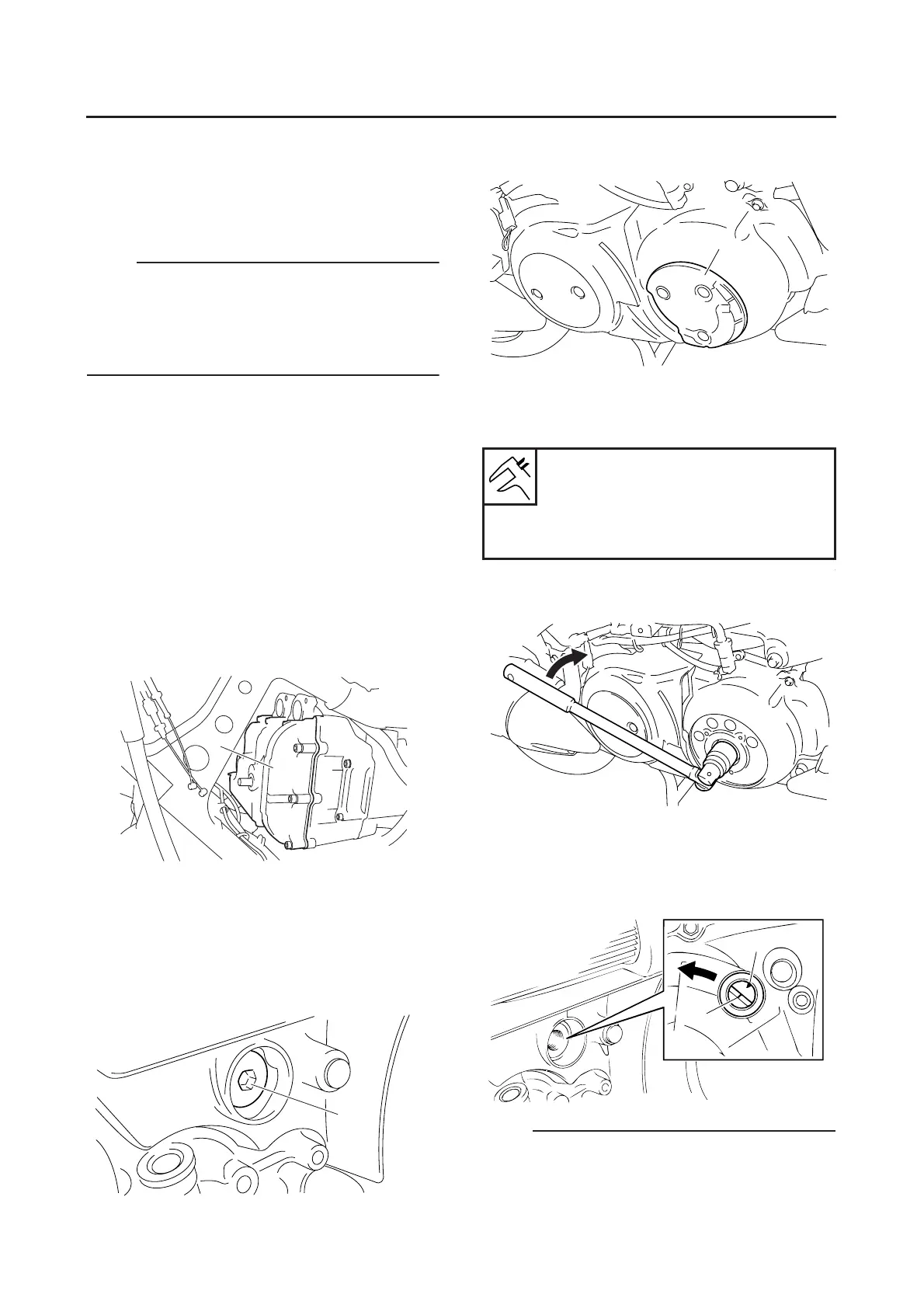
5. Remove:
● Timing plug “1”
6. Remove:
● V-belt case cover “1”
7. Measure:
● Valve clearance
Out of specification → Adjust.
▼▼▼▼▼▼▼▼▼▼▼▼▼▼▼▼▼▼▼▼▼
a. Turn the crankshaft counterclockwise.
b. When piston #1 is at TDC on the compres-
sion stroke, align the TDC mark “a” on the
generator rotor with the mark “b” on the
crankcase.
NOTE:
● TDC on the compression stroke can be found
when the camshaft lobes are turned away from
each other.
1
1
Valve clearance (cold)
Intake
0.15–0.20 mm (0.0059–0.0079 in)
Exhaust
0.25–0.30 mm (0.0098–0.0118 in)
1
a
b

 Loading...