ELECTRICAL COMPONENTS
8-117
▲▲▲▲▲▲▲▲▲▲▲▲▲▲▲▲▲▲▲▲▲
2. Check:
● Operation of the horn
The horn fails to sound → check the step (3).
▼▼▼▼▼▼▼▼▼▼▼▼▼▼▼▼▼▼▼▼▼
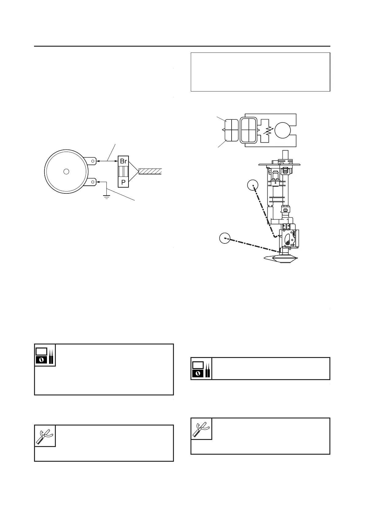
a. Disconnect the horn coupler at the horn.
b. Connect a jumper lead “1” to the brown termi-
nal in the horn coupler and the horn terminal.
c. Turn the main switch to “ON”.
d. Check that the horn does sound.
▲▲▲▲▲▲▲▲▲▲▲▲▲▲▲▲▲▲▲▲▲
EAS28230
CHECKING THE FUEL SENDER
1. Remove:
● Fuel pump
(from the fuel tank)
2. Disconnect:
● Fuel sender coupler
(from the wire harness)
3. Check:
● Fuel sender resistance
Out of specification → Replace.
▼▼▼▼▼▼▼▼▼▼▼▼▼▼▼▼▼▼▼▼▼
a. Connect the pocket tester (Ω× 1) to the fuel
sender terminal as shown.
b. Measure the fuel sender resistance.
▲▲▲▲▲▲▲▲▲▲▲▲▲▲▲▲▲▲▲▲▲
EAS28240
CHECKING THE SPEED SENSOR
1. Check:
● Speed sensor output voltage
Out of specification → Replace.
▼▼▼▼▼▼▼▼▼▼▼▼▼▼▼▼▼▼▼▼▼
a. Connect the pocket tester (DC 20 V) to the
speed sensor coupler (wire harness side) as
shown.
Fuel sender resistance (up posi-
tion F “A”)
19–21Ω at 20°C (68°F)
Fuel sender resistance (down po-
sition E “B”)
137–143Ω at 20°C (68°F)
Pocket tester
90890-03112
Analog pocket tester
YU-03112-C
1
1
Positive tester probe
Green “1”
Negative tester probe
Black “2”
Output voltage reading cycle
0 V–5 V–0 V–5 V–0 V
Pocket tester
90890-03112
Analog pocket tester
YU-03112-C
B
G
B
R/L
1
2
A
B
 Loading...