ENGINE
3-5
NOTE:
● The thickness “a” of each valve pad is marked
in hundredths of millimeters on the side that
touches the valve lifter.
● Since valve pads of various sizes are originally
installed, the valve pad number must be round-
ed in order to reach the closest equivalent to
the original.
c. Round off the original valve pad number ac-
cording to the following table.
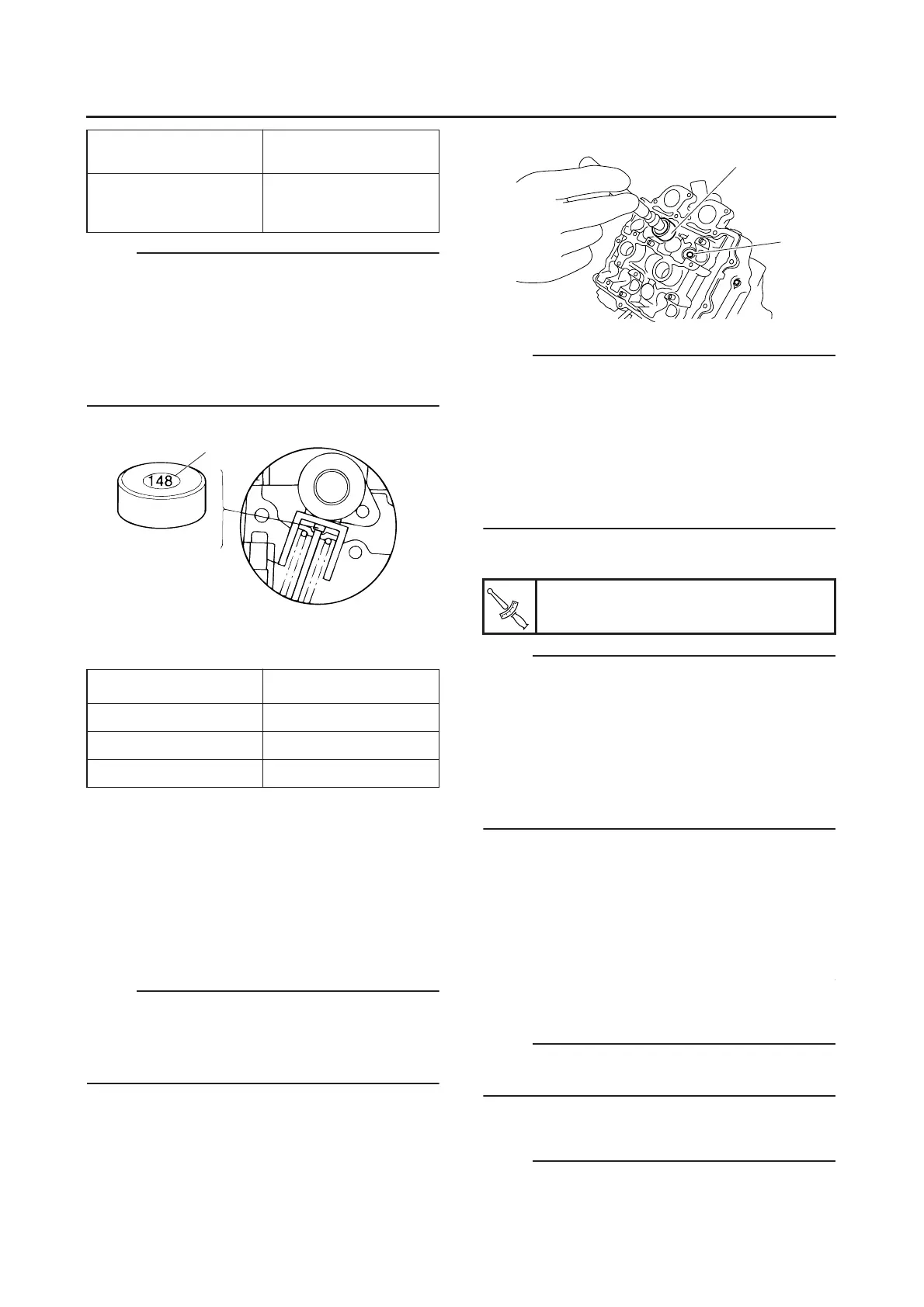
EXAMPLE:
Original valve pad number = 148 (thickness =
1.48 mm (0.058 in))
Rounded value = 150
d. Locate the rounded number of the original
valve pad and the measured valve clearance
in the valve pad selection table. The point
where the column and row intersect is the
new valve pad number.
NOTE:
The new valve pad number is only an approxi-
mation. The valve clearance must be measured
again and the above steps should be repeated if
the measurement is still incorrect.
e. Install the new valve pad “1” and the valve lift-
er “2”.
NOTE:
● Lubricate the valve pad with molybdenum
disulfide grease.
● Lubricate the valve lifter with molybdenum
disulfide oil.
● The valve lifter must turn smoothly when rotat-
ed by hand.
● Install the valve lifter and the valve pad in the
correct place.
f. Install the exhaust and intake camshafts, tim-
ing chain and camshaft caps.
NOTE:
● Refer to “CAMSHAFTS” on page 5-6.
● Lubricate the camshaft bearings, camshaft
lobes and camshaft journals.
● First, install the exhaust camshaft.
● Align the camshaft marks with the camshaft
cap marks.
● Turn the crankshaft counterclockwise several
full turns to seat the parts.
g. Measure the valve clearance again.
h. If the valve clearance is still out of specifica-
tion, repeat all of the valve clearance adjust-
ment steps until the specified clearance is
obtained.
▲▲▲▲▲▲▲▲▲▲▲▲▲▲▲▲▲▲▲▲▲
10.Install:
● All removed parts
NOTE:
For installation, reverse the removal procedure.
Note the following points.
EAS20570
SYNCHRONIZING THE THROTTLE BODIES
NOTE:
Prior to synchronizing the throttle bodies, the
valve clearance and the engine idling speed
Valve pad thickness
1.20–2.40 mm
(0.0472–0.0945 in)
Available valve pads
25 thicknesses in 0.05
mm (0.002 in) incre-
ments
Last digit Rounded value
0 or “2” 0
55
810
a
Camshaft cap bolt
10 Nm (1.0 m•kg, 7.2 ft•lb)
2
1
T
R
.
.

 Loading...