ABS (Anti-Lock Brake System)
4-49
EAS22770c
INSTALLING THE HYDRAULIC UNIT
Proceed in the reverse order of disassembly.
Pay attention to the following items.
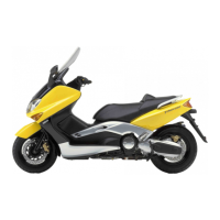
1. Install:
● Hydraulic unit
NOTE:
● When tightening the hydraulic unit nuts, first
temporarily tighten the front nuts, and then
tighten the rear nut and the front nuts to speci-
fication in the order given.
● Do not allow any foreign materials to enter the
hydraulic unit or the brake hoses when install-
ing the hydraulic unit.
CAUTION:
ECA15B1021
Do not remove the rubber plugs or bolts
(M10×1.25) installed in the union bolt holes
before installing the hydraulic unit.
NOTE:
Do not allow any foreign materials to enter the
hydraulic unit or the brake hoses when installing
the hydraulic unit.
2. Remove:
● Rubber plugs or bolts (M10 × 1.25)
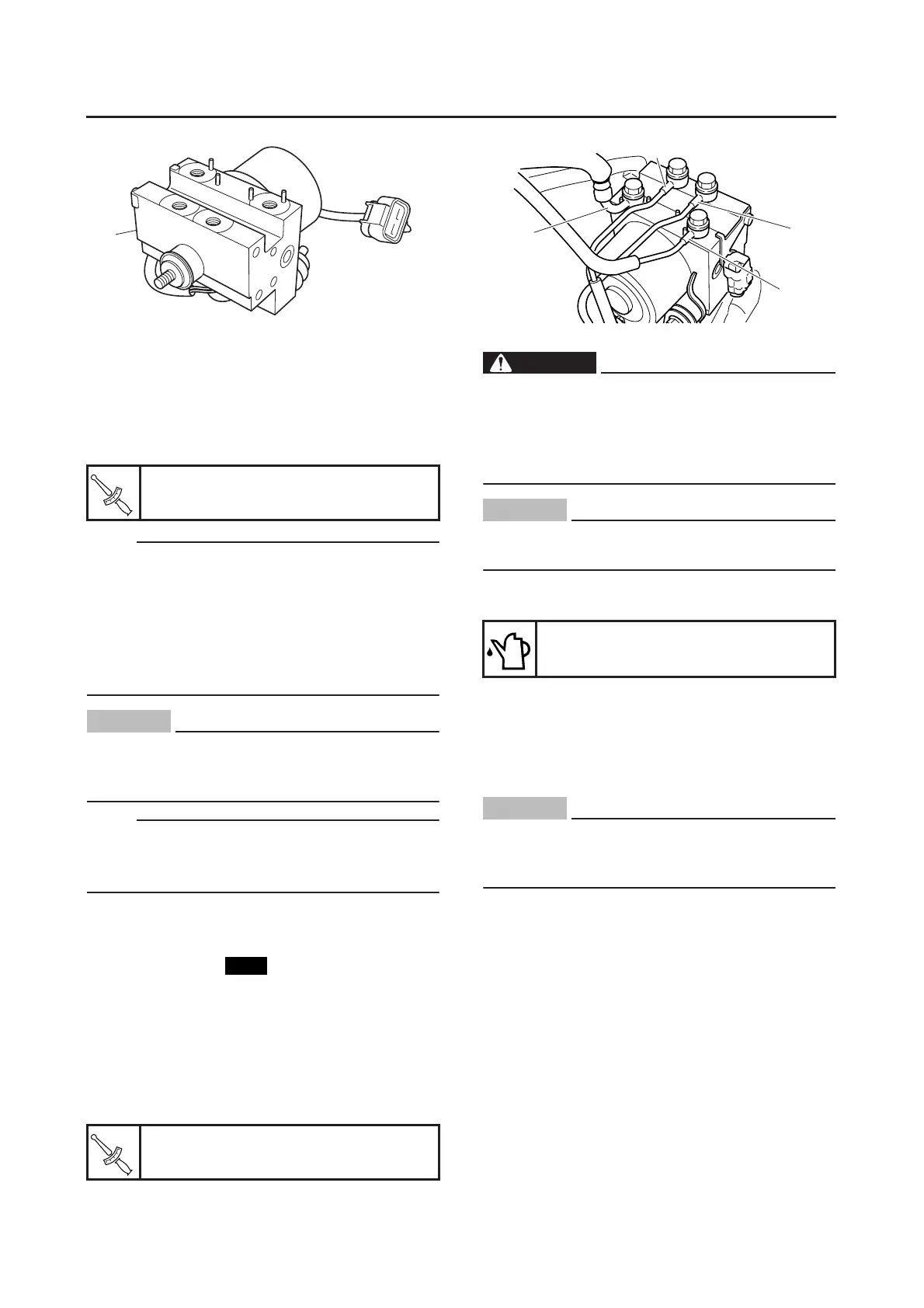
3. Install:
● Copper washer
● Brake hose “1” (to the rear brake caliper)
● Brake hose “2” (from the rear brake master
cylinder)
● Brake hose “3” (to the front brake caliper)
● Brake hose “4” (from the front brake master
cylinder)
● Union bolt
WARNING
EWA13940
The brake hoses to the front and rear brake
calipers can be distinguished by the rubber
at the end of each hose. Be sure to connect
each brake hose to the correct union bolt
hole.
CAUTION:
ECA14760
To route the front and rear brake hoses, refer
to “CABLE ROUTING” on page 2-35.
4. Fill:
● Brake master cylinder reservoir
5. Bleed the brake system.
6. Check the operation of the hydraulic unit ac-
cording to the brake lever and the brake ped-
al response. (Refer to “HYDRAULIC UNIT
OPERATION TEST” on page 4-49.)
CAUTION:
ECA14770
Always check the operation of the hydraulic
unit according to the brake lever and the
brake pedal response.
EAS22800
HYDRAULIC UNIT OPERATION TEST
The reaction-force pulsating action generated in
the brake levers when the ABS is activated can
be tested when the vehicle is stopped.
The hydraulic unit operation can be tested by the
following two methods.
● Hydraulic unit operation test 1: this test gener-
ates the same reaction-force pulsating action
that is generated in the brake levers when the
ABS is activated.
● Hydraulic unit operation test 2: this test checks
the function of the ABS after the system was
disassembled, adjusted, or serviced.
Hydraulic unit bracket bolt
16 Nm (1.6 m•kg, 11 ft•lb)
Brake hose union bolt
30 Nm (3.0 m•kg, 22 ft•lb)
1
T
R
.
.
New
T
R
.
.
Recommended brake fluid
DOT 4
2
1
3
4

 Loading...