FUEL INJECTION SYSTEM
8-45
EAS27471
TROUBLESHOOTING DETAILS
This section describes the measures per fault code number displayed on the meter. Check and service
the items or components that are the probable cause of the malfunction following the order given.
After the check and service of the malfunctioning part has been completed, reset the meter display ac-
cording to the reinstatement method.
Fault code No.:
Code number displayed on the meter when the engine failed to work normally. Refer to “Self-Diagnostic
Function table”.
Diagnostic code No.:
Diagnostic code number to be used when the diagnostic mode is operated. Refer to “DIAGNOSTIC
MODE” on page 8-38.
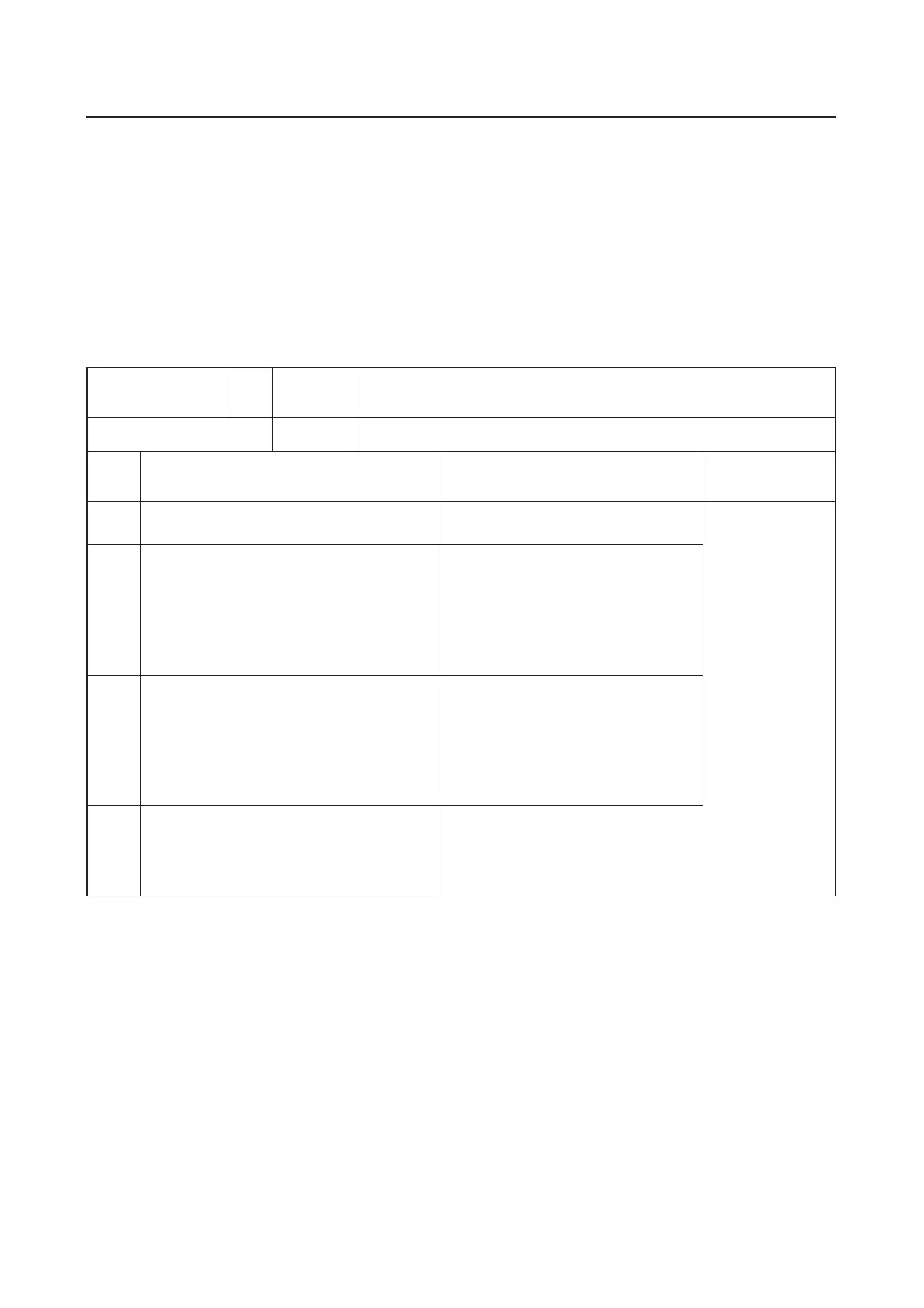
Fault code No. 12 Symptom
No normal signals are received from the crankshaft position
sensor.
Diagnostic code No.
Order Item/components and probable cause Check or maintenance job
Reinstatement
method
1 Installed condition of crankshaft position
sensor
Check the installed area for loose-
ness or pinching.
Cranking the
engine.
2 Connected state of connector
● Crankshaft position sensor coupler
● Main wire harness ECU (engine)
coupler
● Check the coupler for any pins
that may have pulled out.
● Check the locking condition of
the coupler.
● If there is a malfunction, repair it
and connect it securely.
3 Open or short circuit in wire harness.
● Repair or replace if there is an
open or short circuit.
● Between the sensor coupler
and ECU coupler.
(Black/Yellow–Black/Yellow)
(Black/Blue–Black/Blue)
4 Defective crankshaft position sensor.
● Replace if defective.
Refer to “CHECKING THE
CRANKSHAFT POSITION SEN-
SOR” on page 8-114.
 Loading...