ABS (ANTI-LOCK BRAKE SYSTEM) (XP500A)
8-73
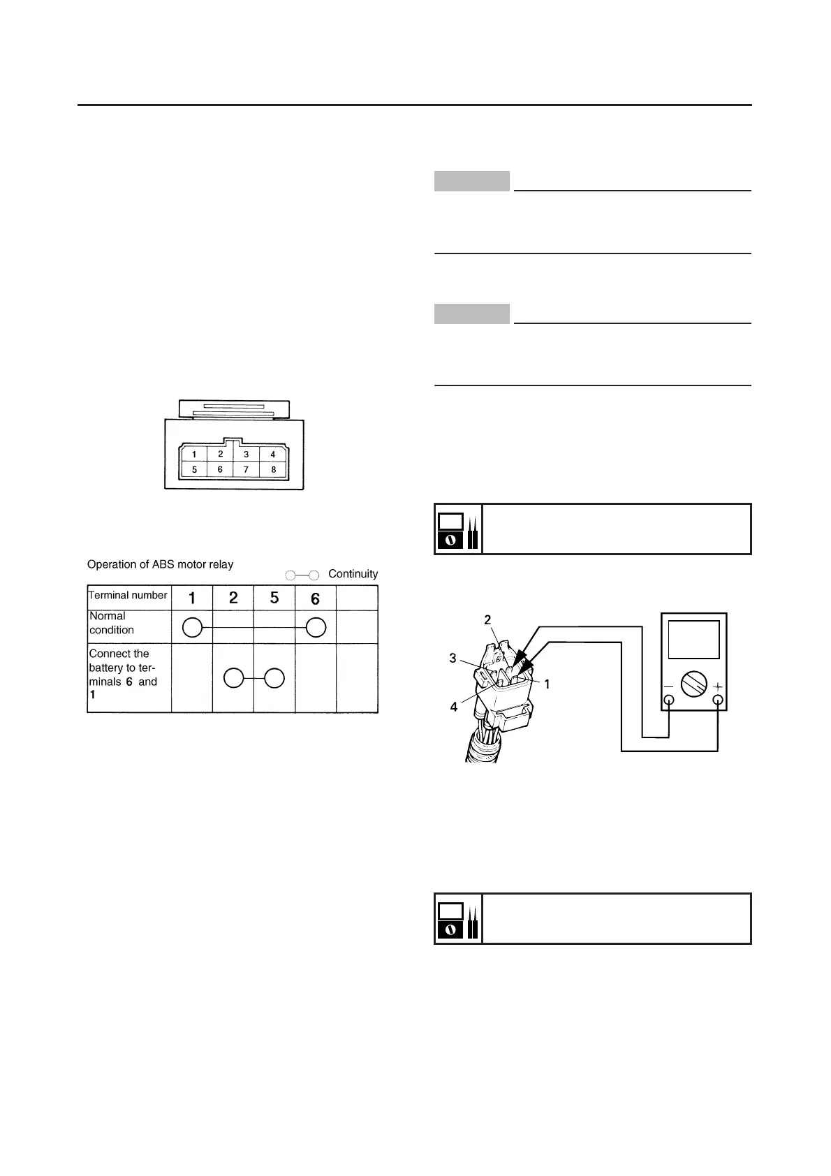
● Connect the positive battery terminal to termi-
nal “6” and the negative battery terminal to
terminal “1”, and then check for continuity be-
tween terminals “2” and “5” of the ABS motor
relay.
Positive tester probe → Terminal “2”
Negative tester probe → Terminal “5”
Tester reading is “∞”. → Replace the fail-safe
relay.
● When connecting the battery and the ABS
motor relay terminals, be careful not to
short-circuit the positive and negative battery
terminals.
EAS15B4887b
[D-3] MAINTENANCE OF THE FRONT
WHEEL SENSOR AND SENSOR ROTOR
CHECKING THE FRONT WHEEL SENSOR
AND SENSOR ROTOR
Refer to “CHECKING THE FRONT WHEEL
SENSOR AND SENSOR ROTOR (XP500A)”.
EAS15B4887c
[D-4] MAINTENANCE OF THE REAR WHEEL
SENSOR AND SENSOR ROTOR
CHECKING THE REAR WHEEL SENSOR
AND SENSOR ROTOR
Refer to “CHECKING THE FRONT WHEEL
SENSOR AND SENSOR ROTOR (XP500A)”.
EAS15B4887d
[D-5] MAINTENANCE OF THE HYDRAULIC
UNIT
CAUTION:
ECA15B1006
Do not remove the hydraulic unit to check
the resistance of the solenoid valves and the
ABS motor for continuity.
Checking the resistance of the solenoid
valves and ABS motor for continuity
CAUTION:
ECA15B1007
When check the hydraulic unit solenoid relay
and ABS motor, do not remove the brake
hoses.
1. Measure:
● Resistance of the solenoid valve (front)
Connect a pocket tester (Ω× 1) to the termi-
nals of the solenoid valve (front).
Positive tester probe → Terminal “1”
Negative tester probe → Terminal “2”
Out of specification Replace the hydraulic
unit.
2. Measure:
● Resistance of the solenoid valve (rear)
Connect the pocket tester (Ω× 1) to the termi-
nals of solenoid valve (rear).
Positive tester probe → Terminal “4”
Negative tester probe → Terminal “3”
Out of specification → Replace the hydraulic
unit.
3. Check:
● ABS motor for continuity
Connect the pocket tester (Ω× 1) to the termi-
nals of the ABS motor coupler.
Solenoid valve resistance
2.96–3.20 at 20 °C (68 °F)
Solenoid valve resistance
2.96–3.20 at 20 °C (68 °F)
 Loading...