ELECTRICAL COMPONENTS
8-114
e. Crank the engine by pushing the starter
switch and gradually increase the spark gap
until a misfire occurs.
▲▲▲▲▲▲▲▲▲▲▲▲▲▲▲▲▲▲▲▲▲
EAS28120
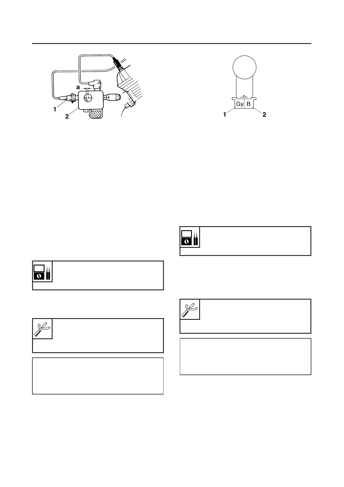
CHECKING THE CRANKSHAFT POSITION
SENSOR
1. Disconnect:
● Crankshaft position sensor coupler
(from the wire harness)
2. Check:
● Crankshaft position sensor resistance
Out of specification → Replace the crank-
shaft position sensor.
▼▼▼▼▼▼▼▼▼▼▼▼▼▼▼▼▼▼▼▼▼
a. Connect the pocket tester (Ω × 100) to the
crankshaft position sensor coupler as shown.
b. Measure the crankshaft position sensor re-
sistance.
▲▲▲▲▲▲▲▲▲▲▲▲▲▲▲▲▲▲▲▲▲
EAS28130
CHECKING THE LEAN ANGLE SENSOR
1. Remove:
● Lean angle sensor
(from the bracket.)
2. Check:
● Lean angle sensor out put voltage
Out of specification → Replace.
▼▼▼▼▼▼▼▼▼▼▼▼▼▼▼▼▼▼▼▼▼
a. Connect the lean angle sensor coupler to the
wireharness.
b. Connect the pocket tester (DC 20 V) to the
lean angle sensor coupler as shown.
1. Spark plug gap
Crankshaft position sensor resis-
tance
189–231 Ω (Gy-B)
Pocket tester
90890-03112
Analog pocket tester
YU-03112-C
Positive tester probe
Gray “1”
Negative tester probe
Black “2”
Lean angle sensor out put voltage
Less than 45° “a”: 0.4–1.4 V
More than 45° “b”: 3.8–4.2 V
Pocket tester
90890-03112
Analog pocket tester
YU-03112-C
Tester positive probe
Blue “1”
Negative tester probe
Yellow/Green “2”

 Loading...