CRANKCASE AND CRANKSHAFT
5-63
3. Check:
● Crankcase
Cracks/damage → Replace.
● Oil delivery passages
Obstruction → Blow out with compressed air.
EAS15B4207
CHECKING THE TIMING CHAIN
1. Check:
● Timing chain
Damage/stiffness → Replace the timing
chain and camshaft sprockets as a set.
EAS26090
CHECKING THE CRANKSHAFT AND
CONNECTING RODS
1. Measure:
● Crankshaft runout
Out of specification → Replace the crank-
shaft.
2. Check:
● Crankshaft journal surfaces
● Crankshaft pin surfaces
● Bearing surfaces
Scratches/wear → Replace the crankshaft.
3. Measure:
● Crankshaft-pin-to-big-end-bearing clearance
Out of specification → Replace the big end
bearings.
▼▼▼▼▼▼▼▼▼▼▼▼▼▼▼▼▼▼▼▼▼
The following procedure applies to all of the
connecting rods.
CAUTION:
ECA13930
Do not interchange the big end bearings and
connecting rods. To obtain the correct
crankshaft-pin-to-big-end-bearing clear-
ance and prevent engine damage, the big
end bearings must be installed in their origi-
nal positions.
c. Clean the big end bearings, crankshaft pins,
and the inside of the connecting rod halves.
d. Install the big end upper bearing into the con-
necting rod and the big end lower bearing into
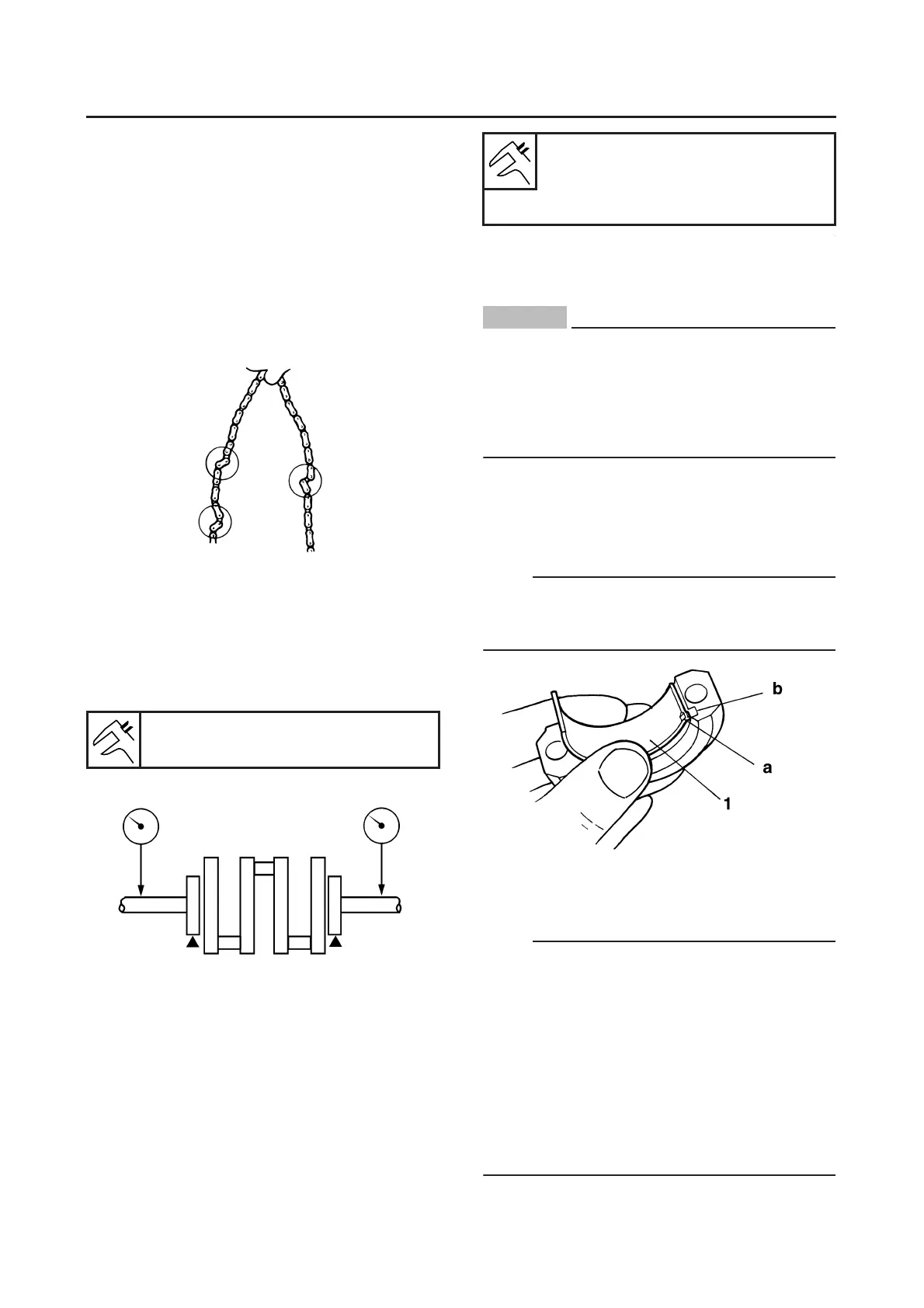
the connecting rod cap.
NOTE:
Align the projections “a” on the big end bearings
with the notches “b” in the connecting rod and
connecting rod cap.
e. Put a piece of Plastigauge® on the crank-
shaft pin.
f. Assemble the connecting rod halves.
NOTE:
● Do not move the connecting rod or crankshaft
until the clearance measurement has been
completed.
● Lubricate the bolts threads and nut seats with
molybdenum disulfide grease.
● Make sure the “Y” mark “c” on the connecting
rod faces towards the left side of the crank-
shaft.
● Make sure the characters “d” on both the con-
necting rod and connecting rod cap are
aligned.
Runout limit C
0.030 mm (0.0012 in)
Journal oil clearance (using plas-
tigauge®)
0.040–0.082 mm (0.0016–0.0032
in)
 Loading...