ELECTRICAL COMPONENTS
8-116
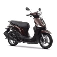
b. Measure the stator coil resistance.
▲▲▲▲▲▲▲▲▲▲▲▲▲▲▲▲▲▲▲▲▲
EAS28170
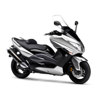
CHECKING THE CHARGING VOLTAGE
1. Check:
● Charging voltage
Out of specification → Correct the stator coil
condition.
Refer to “CHECKING THE STATOR COIL”
on page 8-115.
NOTE:
Make sure the battery is fully charged.
▼▼▼▼▼▼▼▼▼▼▼▼▼▼▼▼▼▼▼▼▼
a. Set the digital tachometer to the ignition coil
of cylinder #1.
b. Connect the pocket tester (AC 20 V) to the
battery terminal as shown.
c. Start the engine and let it run at approximate-
ly 5000 r/min.
d. Measure the charging voltage.
▲▲▲▲▲▲▲▲▲▲▲▲▲▲▲▲▲▲▲▲▲
EAS28180
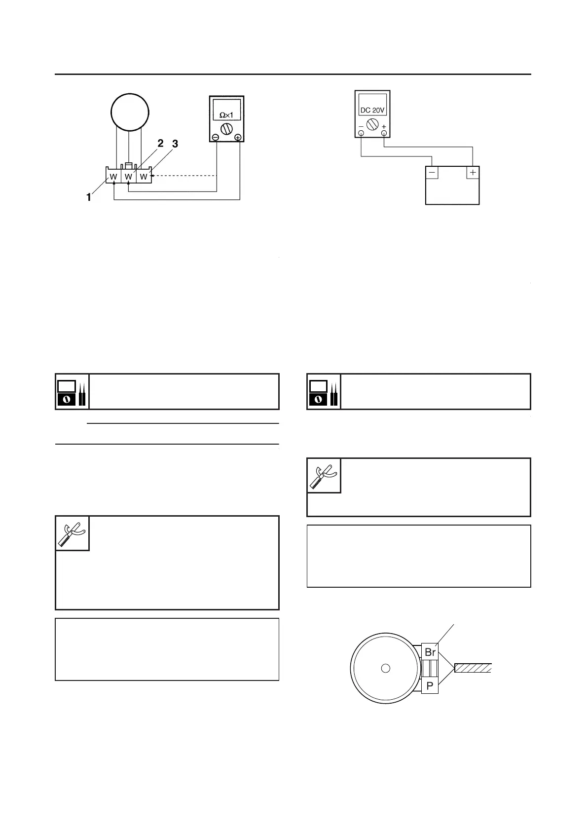
CHECKING THE HORN
1. Check:
● Horn voltage
Out of specification → Properly connect or re-
pair the signaling system’s wiring.
▼▼▼▼▼▼▼▼▼▼▼▼▼▼▼▼▼▼▼▼▼
a. Connect the pocket tester (20V DC) to the
horn terminal.
b. Turn the main switch to “ON”.
c. Measure the voltage (DC 12 V) of brown at
the horn coupler.
Rectifier/regulator input voltage
above 14 V at 5000 r/min
Pocket tester
90890-03112
Analog pocket tester
YU-03112-C
Digital tachometer
90890-06760
YU-39951-B
Positive tester probe
Positive battery terminal
Negative tester probe
Nagative battery terminal
Horn voltage
12V
Pocket tester
90890-03112
Analog pocket tester
YU-03112-C
Tester positive probe
Brown “1”
Negative tester probe
Ground
1
 Loading...