 Loading...
Do you have a question about the Yamaha 2007 XP500 and is the answer not in the manual?
| Displacement | 499 cc |
|---|---|
| Compression Ratio | 11.0:1 |
| Fuel System | Fuel Injection |
| Ignition | TCI |
| Front Suspension | Telescopic fork |
| Rear Suspension | Swingarm |
| Front Tire | 120/70-15 |
| Rear Tire | 160/60-15 |
| Seat Height | 800mm |
| Wheelbase | 1, 580 mm |
| Length | 2, 230mm |
| Width | 775 mm |
| Engine Type | Liquid-cooled, 4-stroke |
| Transmission | Automatic |
| Front Brake | Dual disc |
| Rear Brake | Single disc |
| Fuel Tank Capacity | 15 liters |
Details on vehicle and model identification, including VIN and model label location.
Overview of key features like Fuel Injection (FI) and Anti-Lock Brake System (ABS).
Guidelines for preparation, parts, gaskets, seals, O-rings, lock washers, and circlips.
Procedures for checking leads, couplers, and connectors for stains, rust, and moisture.
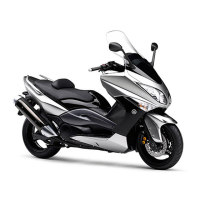
List of necessary special tools for tune-up and assembly, including part numbers.
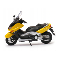
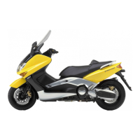
Details on model, dimensions (length, width, height, wheelbase), and weight.
Engine type, displacement, bore, stroke, compression ratio, fuel, oil, and cooling system details.
Specifications for wheels, tires, brakes, steering, and suspension systems.
Details on voltage, ignition system, ECU, coils, spark plugs, magneto, rectifier, battery, and lights.
General and engine-specific tightening torque values for various fasteners.
Specifies lubrication points for engine and chassis, and recommended lubricants.
Maintenance schedule and checks for fuel line, spark plugs, valves, filters, and brakes.
Procedures for adjusting valve clearance, throttle bodies, engine idling speed, and checking spark plugs.
Checks for brake fluid, pads, hoses, chain drive oil, steering head, wheels, tires, and cables.
Procedures for checking and charging the battery, fuses, and replacing/adjusting headlight bulbs.
Procedures for removing, disassembling, checking, and installing the front wheel and brake discs.
Procedures for removing, disassembling, checking, and installing the rear wheel and brake discs.
Procedures for removing/replacing brake pads, calipers, master cylinder, and discs.
Procedures for removing/replacing rear brake pads, calipers, and master cylinder.
Procedures for removing, checking, installing, and testing the hydraulic unit and related ABS components.
Procedures for removing, checking, and installing the handlebar and related controls.
Procedures for removing, disassembling, checking, and assembling front fork legs.
Procedures for removing, checking, and adjusting the steering head and related components.
Procedures for removing, handling, disposing, checking, and installing the rear shock absorber.
Procedures for removing the exhaust pipe and the engine assembly.
Procedures for removing, checking, and installing camshafts and related components.
Procedures for removing, checking, and installing the cylinder head and gasket.
Procedures for removing, checking, and installing valves, springs, and related parts.
Procedures for removing, checking, and installing cylinders, pistons, and rings.
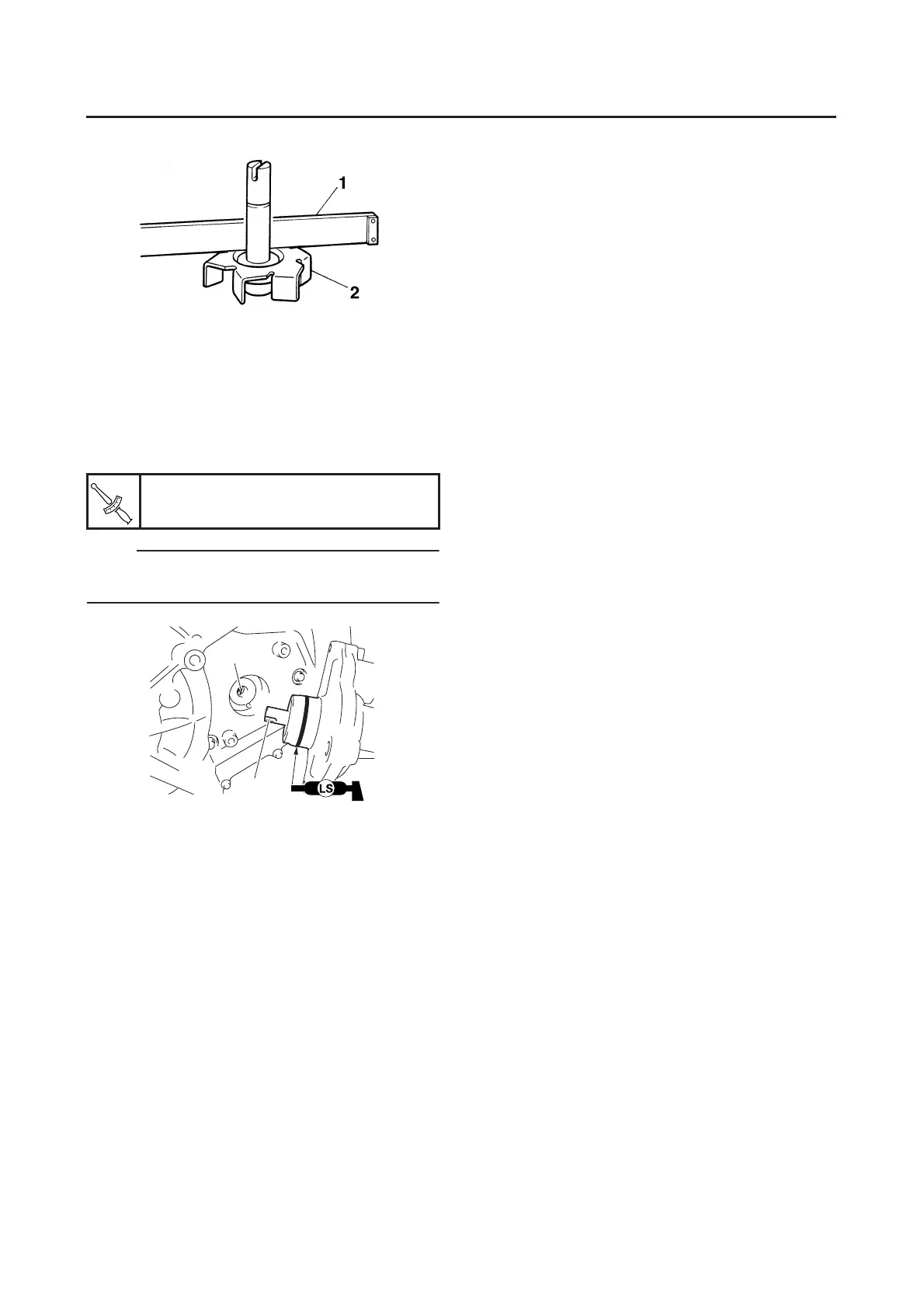
Procedures for removing, checking, and installing the starter clutch and A.C. magneto rotor.
Procedures for removing, checking, assembling, and installing the starter motor.
Procedures for removing, checking, and assembling the oil pump and related components.
Procedures for removing, disassembling, checking, assembling, and installing the clutch.
Procedures for removing, disassembling, checking, and installing the V-belt, sheaves, and related components.
Procedures for removing, disassembling, checking, and installing the crankcase, crankshaft, and connecting rods.
Procedures for removing and checking the transmission, shift drum, and shift forks.
Procedures for removing, checking, assembling, and installing drive chains and related parts.
Procedures for removing, checking, and installing the radiator, fan, and oil cooler.
Procedures for removing, checking, and installing the thermostat and related components.
Procedures for removing, disassembling, checking, assembling, and installing the water pump.
Procedures for removing and installing the fuel tank and fuel pump.
Procedures for removing, disassembling, checking, and adjusting throttle bodies and injectors.
Schematic diagram of the ignition system wiring.
Guide for diagnosing and resolving ignition system failures, such as no spark.
Schematic diagram of the electric starting system wiring.
Explanation of how the starting circuit cut-off system operates and its safety functions.
Steps to diagnose and fix starter motor failures, including checks for fuses, battery, and switches.
Schematic diagram of the charging system wiring.
Steps to diagnose and fix battery charging issues, including checks for fuses, battery, and stator coil.
Schematic diagram of the lighting system wiring.
Steps to diagnose and fix lighting system failures, including bulbs, fuses, switches, and relays.
Schematic diagram of the signaling system wiring.
Steps to diagnose and fix signaling system failures, including turn signals, brake lights, horn, and speedometer.
Schematic diagram of the cooling system wiring.
Steps to diagnose and fix cooling system issues, including fuses, battery, main switch, and fan motor.
Schematic diagram of the fuel injection system wiring.
Explanation of the ECU's self-diagnostic function, fault codes, and fail-safe actions.
Guide for diagnosing normal engine operation issues and utilizing the diagnostic mode.
Schematic diagram of the immobilizer system wiring.
Overview of the immobilizer system, its components, and key registration requirements.
Cases requiring parts replacement and code registration for keys and immobilizer system.
Steps to diagnose issues when the immobilizer system indicator light does not function correctly.
Schematic diagram of the ABS system wiring.
Diagram showing the location of ABS components on the vehicle.
Chart showing the location and color coding of ABS connectors.
Procedures for removing the ECU (ABS) and fail-safe relay.
Steps for checking the ECU (ABS) terminals and resistance.
Procedures for checking the continuity of the fail-safe relay and ABS motor relay.
Procedures for checking the resistance of solenoid valves and the ABS motor.
General guide to ABS troubleshooting, including self-diagnosis and malfunction codes.
Flowchart outlining the basic troubleshooting process for ABS malfunctions.
Steps to determine the cause and location of ABS malfunctions based on warning light behavior.
Table detailing ABS malfunction codes, symptoms, check points, and references.
Guide for basic troubleshooting, covering possible causes and referencing relevant procedures.
Diagnosing and resolving issues related to engine starting problems.
Troubleshooting steps for abnormal engine idling speed.
Diagnosing and resolving issues related to poor engine performance at higher speeds.
Diagnosing and resolving clutch malfunctions, including engagement and slippage issues.
Identifying causes and solutions for engine overheating problems.
Troubleshooting steps for issues related to poor brake performance.
Diagnosing and resolving problems with the front fork legs, including oil leaks and malfunctions.
Troubleshooting steps for issues causing unstable vehicle handling.
Diagnosing and resolving failures in the lighting and signaling systems.