THROTTLE BODIES
7-7
EAS26980
CHECKING THE INJECTORS
1. Check:
● Injectors
Damage → Replace.
EAS26990
CHECKING THE THROTTLE BODIES
1. Check:
● Throttle bodies
Cracks/damage → Replace the throttle bod-
ies as a set.
2. Check:
● Fuel passages
Obstructions → Clean.
▼▼▼▼▼▼▼▼▼▼▼▼▼▼▼▼▼▼▼▼▼
a. Wash the throttle bodies in a petroleum-
based solvent.
Do not use any caustic carburetor cleaning
solution.
b. Blow out all of the passages with com-
pressed air.
▲▲▲▲▲▲▲▲▲▲▲▲▲▲▲▲▲▲▲▲▲
EAS27010
CHECKING THE PRESSURE REGULATOR
OPERATION
1. Check:
● Pressure regulator operation
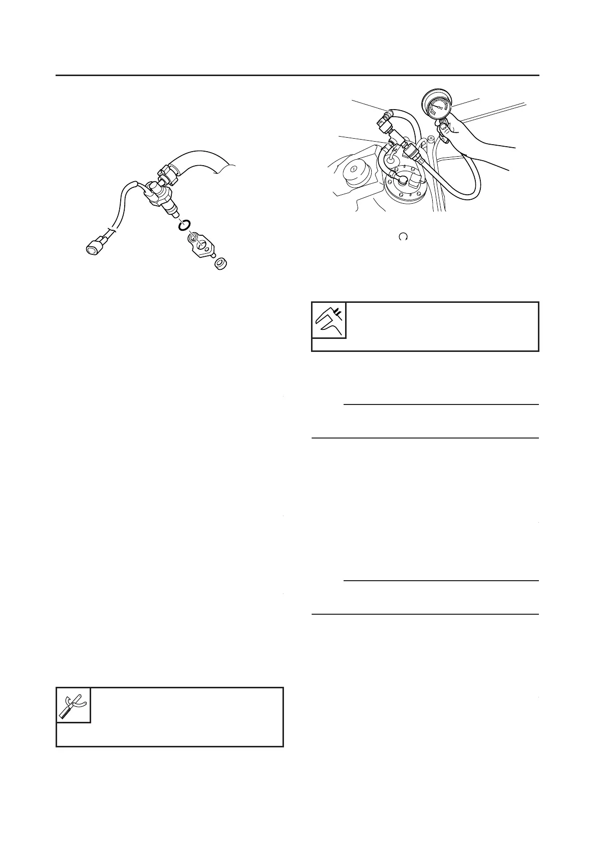
▼▼▼▼▼▼▼▼▼▼▼▼▼▼▼▼▼▼▼▼▼
a. Remove the fuel tank.
Refer to “FUEL TANK” on page 7-1.
b. Disconnect the negative pressure hose “1”
from the pressure regulator at the hose joint.
c. Connect the pressure gauge “2” and adapter
“3” to the fuel injection pipe.
d. Set the main switch to “ON” and the engine
stop switch to “”.
e. Start the engine.
f. Measure the fuel pressure.
Out of specification → Check the fuel hose
connection or replace the fuel pump.
g. Turn the main switch to “OFF”.
h. Remove the pressure gauge and fuel pres-
sure adapter.
NOTE:
Before removing the special tools, place a few
rags in the area under where it will be removed.
i. Install the fuel hose.
j. Install the fuel hose connector cover, fuel
tank cover and seat.
Refer to “GENERAL CHASSIS” on page 4-1.
▲▲▲▲▲▲▲▲▲▲▲▲▲▲▲▲▲▲▲▲▲
EAS27020
ADJUSTING THE THROTTLE POSITION
SENSOR
NOTE:
Before adjusting the throttle position sensor, the
engine idling speed should be properly adjusted.
1. Check:
● Throttle position sensor
Refer to “CHECKING THE THROTTLE PO-
SITION SENSOR” on page 8-119.
2. Adjust:
● Throttle position sensor angle
▼▼▼▼▼▼▼▼▼▼▼▼▼▼▼▼▼▼▼▼▼
a. Turn the main switch to “ON”.
b. Connect the throttle position sensor coupler.
c. Connect the pocket tester to the throttle posi-
tion sensor as shown.
Pressure gauge
90890-03153
Fuel pressure adapter
90890-03181
Fuel pressure
240–260 kPa (240–2.60 kg/cm
2
,
34.2–37.0 psi)
1
2
3

 Loading...