2-48 Phaser 7500 Printer Service Manual
Theory of Operation
Electrical
MCU PWB (PL18.3.6)
The MCU PWB communicates with the Printer Controller and controls the
components used in print operation. The MCU PWB also generates the +3.3VDC
and +2.5VDC voltages that are used by the components from the +5VDC that is
provided by the Main LVPS.
Motor Drive (MD) PWB (PL18.3.7)
The Motor Drive PWB transmits the signals from the MCU PWB to the parts that
are involved with the print operation.
TM Relay PWB (PL18.3.11)
The TM Relay PWB acts as a relay between the Motor Drive PWB and the Tray
Module PWB.
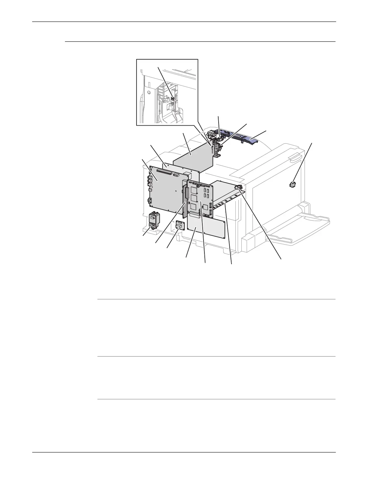
s7500-381
GFI
PB Board
TM Relay Board
MD Board
MCU Board
HVPS (Developer/BCR)
L/H Cover
Interlock Switch
IP Board
HVPS (1st/2nd/DTS)
Main LVPS
Front Cover Interlock Switch
Main Power Switch Chassis Assembly
Control Panel
IBT Front Cover Switch
Thermo Sensor
 Loading...


