Phaser 7500 Printer Service Manual 5-37
Print-Quality Troubleshooting
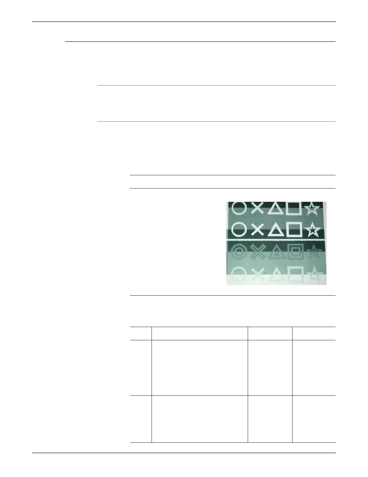
IQ-11 SLED Transfer Failure
Stripes and blank areas (stripes) in an individual color appear repeatedly in sizes of
2.7 mm. They appear by half chip units.
Cause
• + 5 vdc failure. LED Chip failure.
Initial Actions
• Check the paper transfer path.
• Ensure there are no debris on the transfer path.
Troubleshooting Reference
Applicable Parts Example Print
■ LED Print Head, PL2.1.2
■ LVPS, PL18.1.7
■ Motor Drive PWB, PL18.3.7
Troubleshooting Procedure
Step Actions and Questions Yes No
1 Check the power source.
Is 5V output from the Motor Drive
PWB?
■ Pin 518 A4 for Yellow
■ Pin 518 A8 for Magenta
■ Pin 518 B5 for Cyan
■ Pin 518 B1 for Black
Go to step 2. Go to step 3.
2 Check the continuity of the cable
between the Motor Drive MCU and
LED Print Head of the effected color.
Is the continuity between the Motor
Drive PWB and the LED Print Head
normal?
Replace the
LED Print Head
(REP 2.1,
page 8-18).
Replace the
cable.
 Loading...


