EasyManuals Logo
Home>Xerox>Printer>PHASER 7500

Xerox PHASER 7500 Service Manual

Xerox PHASER 7500
992 pages
To Next Page IconTo Next Page
To Previous Page IconTo Previous Page
Page #949 background imageLoading...
Page #949 background image
Phaser 7500 Printer Service Manual 10-49
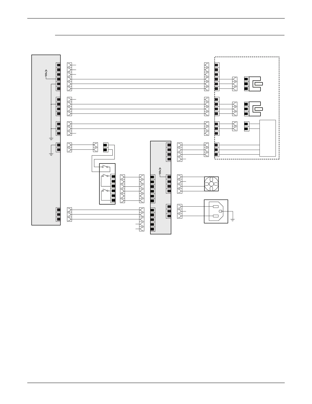
Plug/Jack and Wiring Diagrams
Print Engine - Fuser, LVPS Fan, GFI Switch
MCU Board
P/J431
P/J6J5 P/J31P/J401
P/J4
P/J503
P/J600
s7500-487
1
2
3
4
P/J192
Fuser Exit
Sensor
Main Switch
3
2
1
+5VDC
+24VDC
+24VRTN
/ALRM
N.C.
N.C.
N.C.
B6
B5
B4
B3
5
6
1
2
4
6
5
3
GND
FUSER_EXIT_SNR
B2
B1
10
9
1
2
8
7
6
7
8
P/J190
P/J191
3
2
1
NC_SNR_VINF
NC_SNR_VTEMP
MAIN_SW_STS
READY_POWER_ON
MAIN_POWER_ON
LVPS_FAN_ON
N.C.
N.C.
N.C.
To Motor Driver Board P/J520-8
N.C.
N.C.
A7
A6
9
10
GND
A5
A4
11
2
1
STS_REAR
GND
GND
AC_HOT
AC_HOT
AC_NUT
AC_NUT
A3
12
13
A2
A1
1
2
3
4
5
1
LAMP_MAIN
LVPS
LAMP_SUB
1
2
3
2
3
LAMP_COM
4
P/J550
1
2
3
4
AC-HOT
AC-NUT
N.C.
P/J1
1
2
3
Fuser
STS
LVPS Fan
GFI Switch
+5VDC
+24VDC

Table of Contents

Other manuals for Xerox PHASER 7500

Questions and Answers:

Question and Answer IconNeed help?

Do you have a question about the Xerox PHASER 7500 and is the answer not in the manual?

Xerox PHASER 7500 Specifications

General IconGeneral
BrandXerox
ModelPHASER 7500
CategoryPrinter
LanguageEnglish

Related product manuals