8-78 Phaser 7500 Printer Service Manual
Service Parts Disassembly
REP 8.9 Gear Bracket Assembly
PL8.2.9
1. Remove the ATC Sensor PWB (REP 5.6, page 8-52).
2. Remove the Waste Toner Pipe Assembly (REP 8.6, page 8-75).
3. Remove the Main LVPS (REP 18.7, page 8-194).
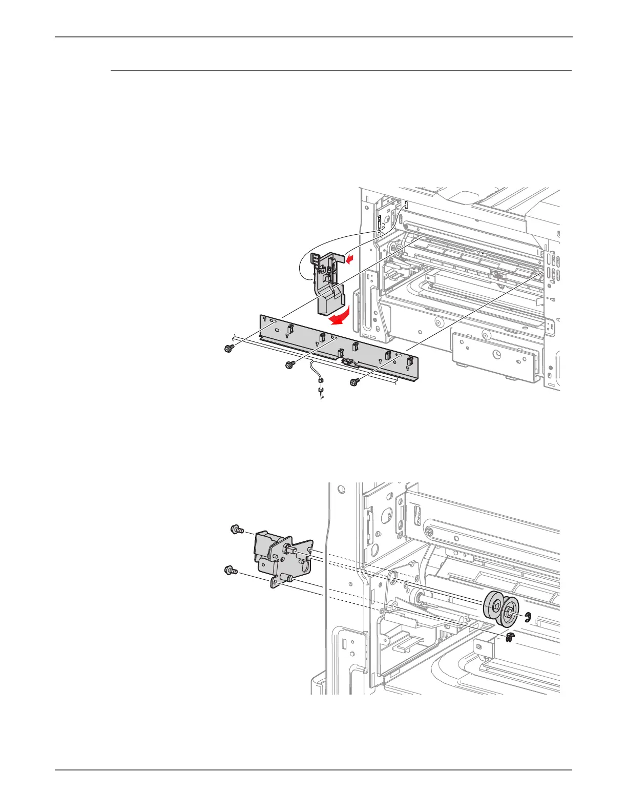
4. Release the one tab hook of the Harness Holder and rotate the Holder
clockwise to remove it.
5. Remove 2 screws (silver, 6mm) that secure the Gear Bracket Assembly.
6. Remove the KL Clip at the rear of the Gear Bracket Assembly and the E- Clip
that secures the Gear.
7. Pull the Gear Bracket Assembly towards the front to remove it and remove the
2 Gears from the rear.
The HVPS cable is positioned behind the shaft.
 Loading...


