Phaser 7500 Printer Service Manual 8-101
Service Parts Disassembly
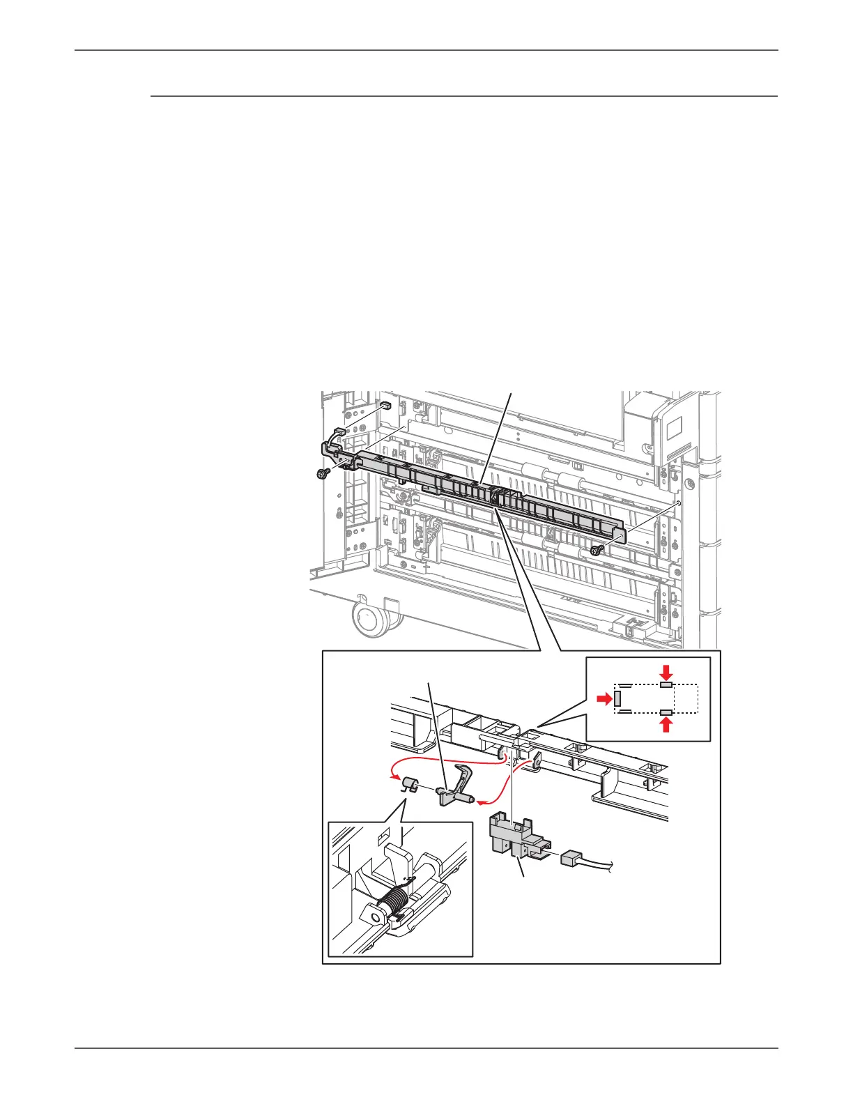
REP 10.13 Chute Assembly/ Tray 4/5 Feed Out Sensor
PL10.11.4/ PL10.11.6
1. Disconnect the wiring harness connector P/J672 that connects the Chute
Assembly to the Tray Module (3T).
2. Remove 2 screws (silver, 8mm) that secure the Chute Assembly to the Tray
Module (3T) and remove the Chute Assembly.
3. Disconnect the wiring harness connector P/J112 that is connected to the Feed
Out Sensor.
4. Release the 3 hooks that secure the Feed Out Sensor to the Chute Assembly
and remove the Feed Out Sensor.
5. Unhook the spring that is attached to the Chute Assembly.
6. Open the 2 installation sections that secure the Actuator to the Chute and
remove the Actuator.
7. Remove the Spring from the Actuator.
Chute Assembly
s7500-165
Actuator
Feed Out Sensor
 Loading...


