8-64 Phaser 7500 Printer Service Manual
Service Parts Disassembly
REP 6.3 Conductor Housing Assembly
PL6.2.8
1. Remove the Top Rear Cover and the Rear Cover (REP 19.6, page 8-217).
2. Remove the Right Cover (REP 19.8, page 8-219).
3. Remove the PWB Chassis Unit (REP 18.10, page 8-197).
4. Remove the HVPS (1st/ 2nd/ DTS) (REP 6.4, page 8-65).
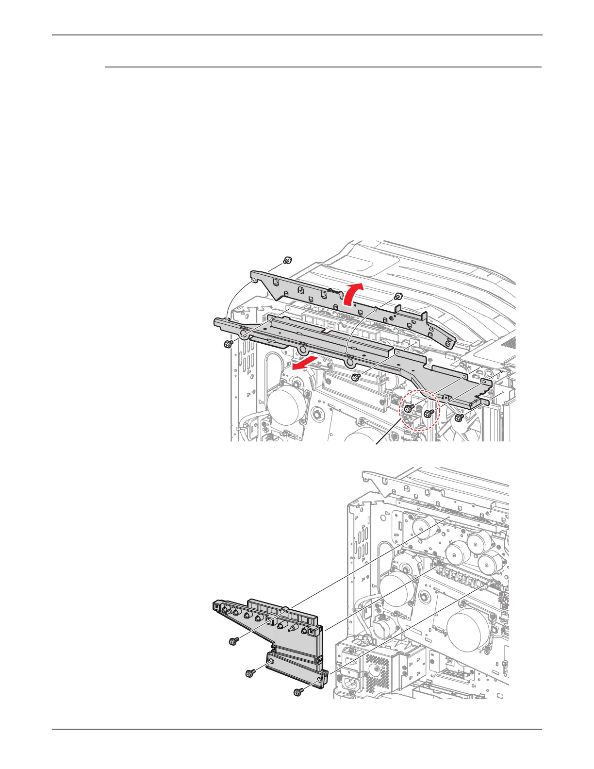
5. Remove 2 screws (silver, 6mm) that secure the Harness Holder and rotate the
Harness Holder.
6. Remove 5 screws (silver, 6mm), and 2 screws (silver, 8mm) that secure the Rear
Upper Frame and remove the Rear Upper Frame.
7. Remove 3 screws (silver, 6mm) that secure the Conductor Housing Assembly
and remove the Conductor Housing Assembly.
 Loading...


