8-40 Phaser 7500 Printer Service Manual
Service Parts Disassembly
REP 4.3 HV Fan
PL4.3.1
1. Remove the PWB Chassis Unit (REP 18.10, page 8-197).
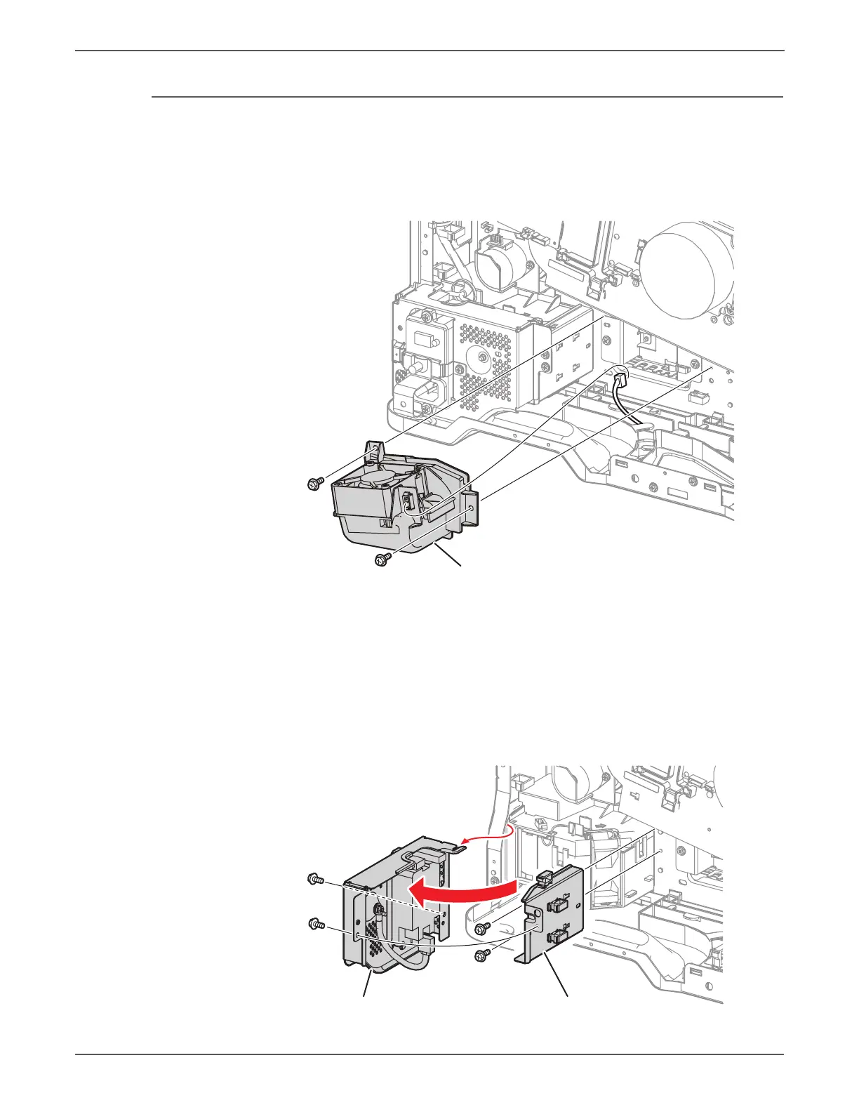
2. Remove 2 screws that secure the Bottom Fan Assembly (PL4.3.6).
3. Disconnect the wiring harness connector and remove the Fan.
Because the GFI Chassis is to be removed with the harness still connected, do
not apply excessive force when performing the next step.
4. Remove 2 screws (silver, 6mm) that secure the GFI Chassis and remove the
GFI Chassis.
5. Remove 2 screws (silver, 6mm) that secure the Bracket, release the harness
from the 3 clamps, and remove the Bracket.
6. Disconnect the wiring harness connector that is connected to the Duct
Assembly.
Rear Bottom Duct Assembly
s7500-482
s7500-094
Bracket
GFI Chassis Assembly
 Loading...


