GASOLINEVEHICLE-ELECTRICAL
COMPONENTSStarter/Generator
19
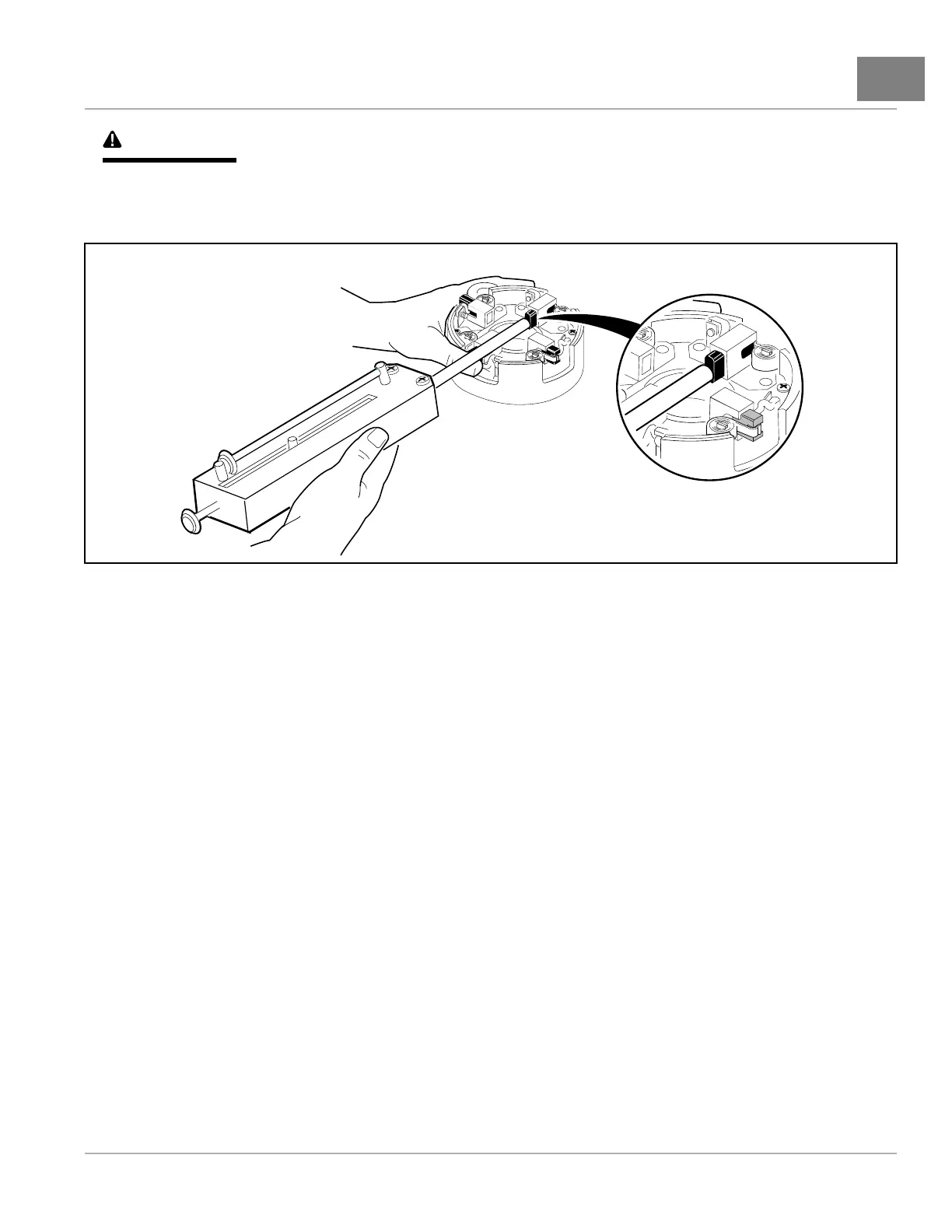
CAUTION
•Whencheckingbrushspringtension,donotpushspringsbeyondthepointtheywouldnormallybeif
therewerenewbrushesinstalled.Exertingexcessiveforceorpushingbrushspringsbeyondtheir
normalmaximumextensionpointwilldamagesprings.
490
Figure19-4BrushSpringTensionTest
STARTER/GENERATORASSEMBLY
1.Installthebrushes(27)intotheholders.Installtheterminalhardware(25)(Figure19-2,Page19-2).
2.Topreventcontactbetweenthebrushesandcommutatorasthecommutatorisinstalled,andpossibledamage
tothebrushes,liftthebrushspringsandpullthebrushesbackfromthecenterofthecommutatorendcover.
Thespringswillrestonthesidesofthebrushesandhelppreventthemfromslidingtowardsthecenterofthe
cover(Figure19-5,Page19-4).
3.Installthecommutatorendcover(23)ontothearmatureshaft.Alignthelocatingpinwiththepinholeinthecover.
InstalltwoM6x180mmbolts(20)andtightento100in·lb(11.3N·m)(Figure19-1,Page19-2).
4.Pushthebrushesdownintotheholders.Positionspringsontheendofthebrushes.Installthebrushcover(30)
thathasthedrainholeinitnexttotheA2terminal.Installtheremainingthreebrushcovers(29)intheopeningsin
thecommutatorendcover(23)(Figure19-2,Page19-2).
2019PrecedentVillager2MaintenanceandServiceManualPage19-3

 Loading...