GASOLINEVEHICLE-CLUTCHESDriveClutch
23
NOTE:Makesurethereisatleasta(minimum)gapof0.020in.(0.51mm)betweeneachendofthemountingpin
andthemountingbolt.
11.Installthreedrivebuttontake-upsprings.
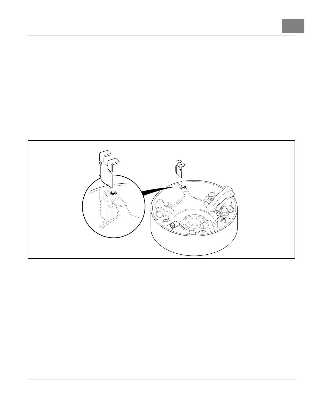
11.1.Installeachspringonright-handsideofthethreebuttonmountingposts(whenlookingintotheinteriorof
theclutchdrivehub,andwiththeribatatwelveo’clockposition)asshown(Figure23-13,Page23-11).
12.Compresseachtake-upspringandinstallthedrivebuttonovertheribandtake-upspring(Figure23-8,Page
23-8).
13.Installadrivebuttonretainingbolt(1)withatwasher(2)througheachbutton(3)andintotherib.Tightenthe
boltsto34in·lb(3.8N·m)(Figure23-8,Page23-8).
14.Installthethrustwasher(9)ontothemoveablesheave(13)(Figure23-3,Page23-4).
15.Installthehubassembly(5)onthemoveablesheave(13)andalignthematchmarksmadebeforedisassembling
theclutch.Pressthehubassemblyonbyhand.
16.Replacethethreeplasticplugs(4)intotheholes(Figure23-3,Page23-4).
3054
Figure23-13CorrectOrientationofDriveButtonTake-upSprings
DRIVECLUTCHINSTALLATION
1.Placethedriveclutchassemblyonthecrankshafttaper.Positionthemountingwashers(2and3)onthebolt(1)
andstarttheboltintothecrankshaft(Figure23-3,Page23-4).SeefollowingNOTE.
NOTE:Thedriveclutchretainingbolthasright-handthreads.Themanufacturerrecommendsreplacingthedrive
clutchretainingboltwheninstallingthedriveclutch.Ifanewboltisnotavailable,cleanthethreadsofthe
originalboltandapplyLoctite
®
242tothethreadedendpriortoinstallation.
2.Tightenthedriveclutchretainingbolt(1)to35ft·lb(47.5N·m)(Figure23-3,Page23-4).
3.Installthestarter/generatorbeltandadjustbelttensionasinstructed.SeeBeltTensionAdjustmentforEFI
Engines,Section19,Page19-13.
4.Installthedrivebeltasinstructed.SeeDriveBeltInstallationonpage23-3.
5.Connectbatteryandsparkplugwire(s).
SeeConnectingtheBattery-GasolineVehiclesonpage1-3.
2019PrecedentVillager2MaintenanceandServiceManualPage23-11

 Loading...