7
FrontSuspensionComponentsSTEERINGANDFRONTSUSPENSION
6.1.Loosenthejamnutsonbothendsofeachdraglink(Figure7-8,Page7-7).
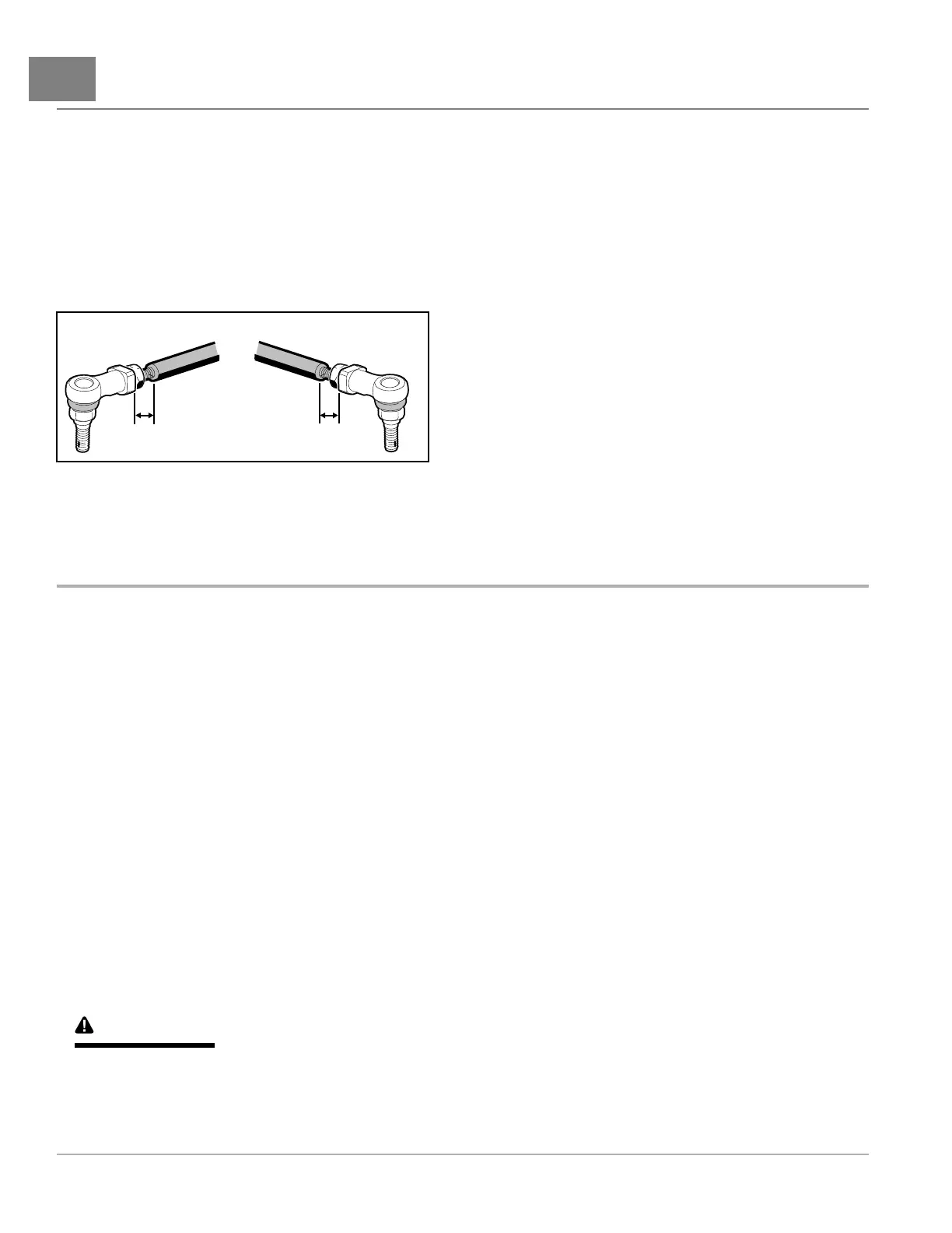
6.2.Rotatebothofthedraglinksequally.T oincreasethetoe-in,rotatebothdraglinkscounterclockwise.To
decreasethetoe-in,rotatebothdraglinksclockwise.Maintainanequaldistancefromtheballjointtothe
endofthethreadsoneachdraglink(Figure7-9,Page7-8).
6.3.Tightenjamnutsto26ft·lb(35N·m).
6.4.Checkthetoe-in,andrepeattheadjustmentprocedureifnecessary.
6.5.Aftertoe-inadjustmentismadeandwithwheelsinthestraightaheadposition,thesteeringwheelshouldbe
atthecenterofitstravel.Thereshouldbeequaltraveltotheleftandright.
2064
Figure7-9AdjustBothDragLinksToAnEqualDistance
FRONTSUSPENSIONCOMPONENTS
SeeGeneralWarningsonpage1-2.
TIERODENDREMOVAL
1.ElectricVehicle:Disconnectthebatteriesanddischargethecontroller.SeeDisconnectingtheBatteries–
ElectricVehiclesonpage1-4.
GasolineVehicle:Disconnectbatteryandsparkplugwire(s).
SeeDisconnectingtheBattery-GasolineVehiclesonpage1-3.
2.Loosenjamnuts(13)toallowlaterrotationofthetierodends(12)(Figure7-10,Page7-12).
3.Removetheretainingnuts(14).
4.Liftmalethreadoftierodfromtheholeinthespindletab.
5.Removethetierodendsfromthesteeringgear.
6.Tominimizecorrosion,applyalightcoatofanti-seizelubricatingcompoundtothethreadswherethetierod
endsareinstalled.
TIERODINSTALLATION
1.Threadtierodends(12)ontosteeringgeartoadepthof1/2inch(12.5mm)(Figure7-10,Page7-12).
WARNING
•Thetierodendsmustbethreadedintotherodatleast5/16ofaninch(8mm).Failuretothreaddeep
enoughmaycausetierodendstoseparatefromtherodduringadjustmentorwhilebeingoperated,
possiblyresultinginlossofvehiclecontrolandseverepersonalinjury.
2.Installtierodends(12)intothespindletabs.Installtheretainingnuts(14)(Figure7-10,Page7-12).
Page7-82019PrecedentVillager2MaintenanceandServiceManual

 Loading...