GASOLINEVEHICLE-CLUTCHESDrivenClutch
23
608
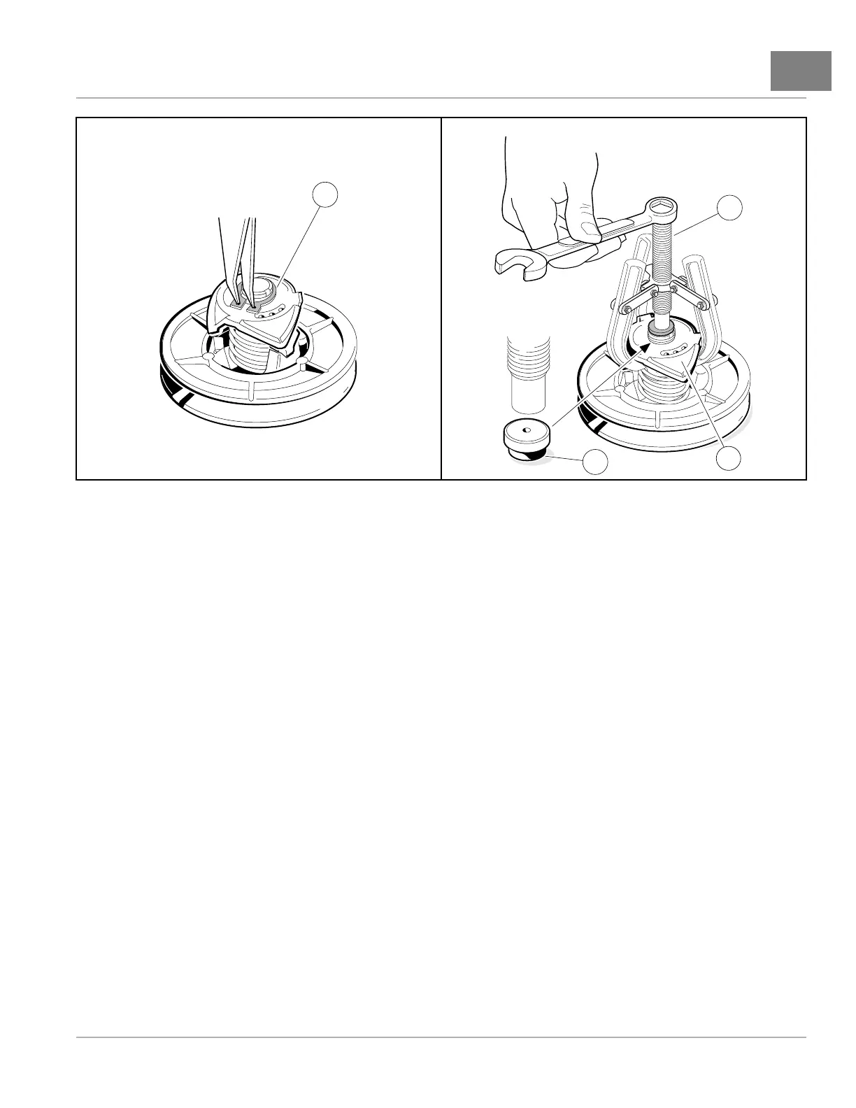
Figure23-15RemoveRetainingRing
609
Figure23-16DrivenClutchDisassembly
DRIVENCLUTCHINSPECTION
1.Inspectthecam(5)forexcessivewear(Figure23-14,Page23-13).Replaceitifnecessary.
2.Inspectthedrivebuttons(8)forexcessivewear.Replaceifnecessary.Toremovethedrivebuttons(8),remove
thesocket-headcapscrews(7)andthenthebuttons.
3.Inspectthesmoothsurfaceonthexedandmoveablesheaves.Sheavesmustbereplacedifsurfacesareworn
morethan0.060in.(1.5mm).
4.Inspectthebronzebearinginthemoveablesheave.Ifthebearingborediameterismorethan1.384in.(35.15
mm),theentiremoveablesheavemustbereplaced.
5.Inspecttheshaftofthexedsheave.Thereshouldbenonoticeablewear.Replacethexedsheaveifitis
worn,scratchedordamaged.
DRIVENCLUTCHASSEMBLY
1.Placethethreedrivebuttons(8)inposition.ApplyonedropofLoctite
®
222toeachofthesocket-headcap
screws(7)andtheninstallandtightenthemto8in·lb(0.9N·m)(Figure23-14,Page23-13).
2.Slidetheacetalwasher(10)andmoveablesheave(9)ontothexedsheave(11).
3.Placetheendofthespring(6)intotheholeinthemoveablesheave(9).
4.Installthekey(4)intothekeywayofthexedsheave(11)shaft.
5.Holdingthecam(5)inpositionforassemblyontheshaft,installtheotherendofthespring(6)intothecenter
springholeofthecam.Rotatethecamuntilthekeywayisalignedwiththekey(4)onthexedsheave,andthen
startthecamontotheshaftapproximately1/4to3/8in.(6.3to9.5mm).
5.1.PressAssemblyProcess:
5.1.1.Placetheclutchassemblyinapressandpositionthecampresstoolonthecam(2)asshown
(Figure23-17,Page23-16).
2019PrecedentVillager2MaintenanceandServiceManualPage23-15

 Loading...