1B-6 Emission Control Devices:
PAIR Reed Valve Removal and Installation
B718H11206008
Removal
1) Remove the fuel tank. Refer to “Fuel Tank Removal
and Installation in Section 1G (Page 1G-9)”.
2) Drain engine coolant and remove the thermostat
connector. Refer to “Thermostat Connector /
Thermostat Removal and Installation in Section 1F
(Page 1F-9)”.
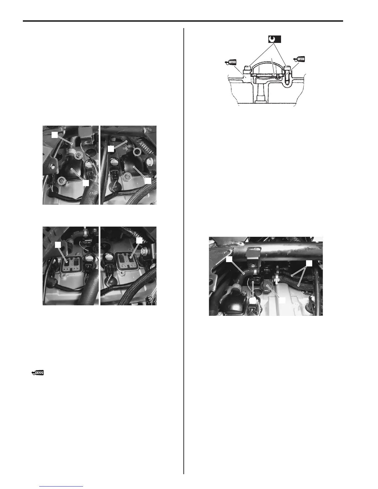
3) Disconnect the hoses (1) and remove the PAIR reed
valve covers (2).
4) Remove the PAIR reed valves (3).
Installation
Install the PAIR reed valve in the reverse order of
removal. Pay attention to the following points:
• Install the PAIR reed valves (1) as shown.
• Apply thread lock to the bolts and tighten them to the
specified torque.
: Thread lock cement 99000–32110
(THREAD LOCK CEMENT SUPER 1322 or
equivalent)
Tightening torque
PAIR reed valve cover bolt (a): 11 N·m (1.1 kgf-m,
8.0 lb-ft)
PAIR Control Solenoid Valve Removal and
Installation
B718H11206001
Removal
1) Remove the fuel tank. Refer to “Fuel Tank Removal
and Installation in Section 1G (Page 1G-9)”.
2) Drain engine coolant and remove the thermostat
connector. Refer to “Thermostat Connector /
Thermostat Removal and Installation in Section 1F
(Page 1F-9)”.
3) Disconnect the PAIR control solenoid valve coupler
(1) and PAIR hoses (2).
4) Remove the PAIR control solenoid valve (3).
Installation
Install the PAIR control solenoid valve in the reverse
order of removal. Pay attention to the following point:
• Connect the PAIR control solenoid valve coupler and
PAIR hoses securely. Refer to “PAIR System Hose
Routing Diagram (Page 1B-4)”.
PAIR System Inspection
B718H11206002
PAIR Hose
1) Remove the fuel tank. Refer to “Fuel Tank Removal
and Installation in Section 1G (Page 1G-9)”.
1
1
2
2
I718H1120023-01
3
3
I718H1120029-01
1
(a)
I718H1120042-01
1
2
2
3
I718H1120007-02

 Loading...


