2D-17 Wheels and Tires:
5) Install the rear wheel speed sensor mounting bolts.
(GSF1250A/SA) Refer to “Rear Wheel Speed
Sensor Removal and Installation in Section 4E
(Page 4E-71)”.
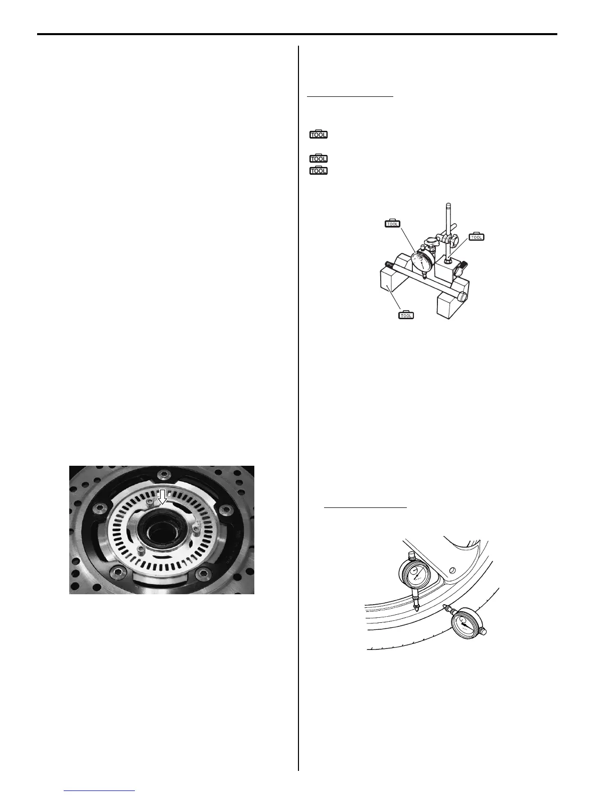
6) Check the clearance between the rear wheel speed
sensor and sensor rotor. (GSF1250A/SA) Refer to
“Rear Wheel Speed Sensor Removal and Installation
in Section 4E (Page 4E-71)”.
Rear Wheel Related Parts Inspection
B718H12406009
Refer to “Rear Wheel Assembly Removal and
Installation (Page 2D-16)”.
Tire
Refer to “Tire Inspection in Section 0B (Page 0B-19)”.
Rear Brake Disc
Refer to “Rear Brake Disc Inspection in Section 4C
(Page 4C-7)”.
Wheel Damper
Refer to “Drive Chain Related Parts Inspection in
Section 3A (Page 3A-5)”.
Sprocket
Refer to “Drive Chain Related Parts Inspection in
Section 3A (Page 3A-5)”.
Dust Seal
Inspect the dust seal lip for wear or damage. If any
defects is found, replace the dust seal with a new one.
Refer to “Rear Wheel Dust Seal / Bearing Removal and
Installation (Page 2D-18)”.
Wheel Axle
Using a dial gauge, check the wheel axle for runout, If
the runout exceeds the limit, replace the axle shaft.
Wheel axle runout
Service limit: 0.25 mm (0.010 in.)
Special tool
(A): 09900–20607 (Dial gauge (1/100 mm, 10
mm))
(B): 09900–20701 (Magnetic stand)
(C): 09900–21304 (V-block (100 mm))
Wheel
1) Remove the brake pads. Refer to “Rear Brake Pad
Replacement in Section 4C (Page 4C-2)”.
2) Make sure that the wheel runout checked as shown
does not exceed the service limit. An excessive
runout is usually due to worn or loosened wheel
bearings and can be reduced by replacing the
bearings. If bearing replacement fails to reduce the
runout, replace the wheel.
3) Install the brake pads. Refer to “Rear Brake Pad
Replacement in Section 4C (Page 4C-2)”.
Wheel rim runout
Service limit (Axial and Radial): 2.0 mm (0.08 in.)
I718H1240037-02
(A)
(B)
(C)
I649G1230034-03
I649G1240014-02

 Loading...


