1D-74 Engine Mechanical:
Balancer Shaft
Inspect the balancer shaft for wear or damage. Replace
the balancer shaft if there is anything unusual.
Conrod Removal and Installation
B718H11406026
Removal
1) Remove the crankshaft assembly from the
crankcase. Refer to “Engine Bottom Side
Disassembly (Page 1D-53)”.
2) Loosen the conrod cap bolts by using a 10 mm, 12
point socket wrench, and tap the conrod cap bolts
lightly with plastic hammer to remove the conrod
cap.
3) Remove the conrods and mark them to identify their
respective cylinders.
4) Remove the bearings (1).
NOTE
• Do not remove the bearings (1) unless
absolutely necessary.
• Make a note of where the bearings are
removed from so that they can be
reinstalled in their original positions.
CAUTION
!
When removing the bearings, be careful not
to scratch the conrods and the bearings.
Installation
1) When installing the bearings into the conrod cap and
conrod, be sure to install the tab “A” first, and then
press in the opposite side of the bearing.
NOTE
Inspect and select the conrod crank pin
bearing if necessary. Refer to “Conrod Crank
Pin Bearing Inspection and Selection
(Page 1D-76)”.
2) Apply molybdenum oil solution to the crank pin and
bearing surface.
CAUTION
!
Be sure to clean the conrod big end.
M/O: Molybdenum oil (Molybdenum oil
solution)
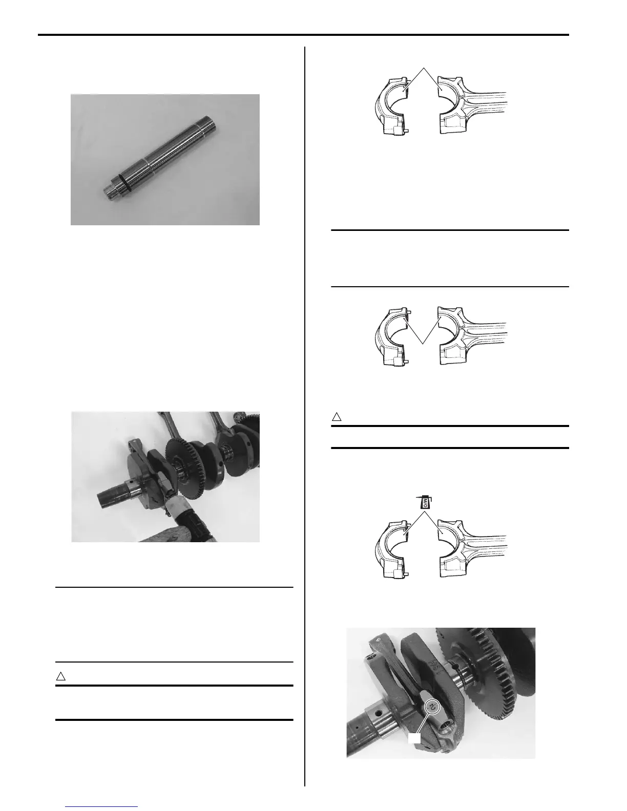
3) When fitting the conrod cap, make sure that I.D.
code “B” on each conrod faces intake side.
I718H1140267-01
I718H1140268-01
1
I718H1140269-01
“A”
I718H1140272-01
I718H1140273-01
“B”
I718H1140274-01

 Loading...


