Engine Mechanical: 1D-17
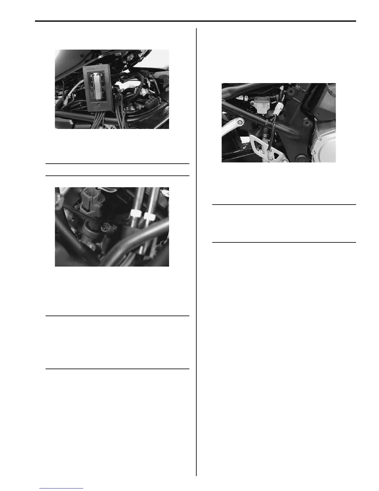
11) Check for the synchronization of vacuum from #1 to
#4 cylinders.
12) Equalize the vacuum of the cylinders by turning each
air screw and keep it running at idling speed.
NOTE
Always set the engine rpm at idle rpm.
13) If the adjustment is not yet correct, remove each air
screw and clean them with a spray-type carburetor
cleaner and blow dry with a compressed air. Also,
clean the air screw passageways.
NOTE
• Slowly turn the air screw in clockwise and
count the number of turns until the screw
is lightly seated.
• Make a note of how many turns were made
in order that the screw can be reset
correctly after cleaning.
14) Repeat the procedures from 4) to 12).
15) Close the SDS tool and turn the ignition switch OFF.
16) Disconnect the vacuum tester and reinstall the
removed parts.
17) After compleating the throttle valve synchronization,
clear the DTC and reset the ISC learned valve using
SDS tool. Refer to “ISC Valve Preset and Opening
Initialization in Section 1C (Page 1C-6)”.
Use of Mode Select Switch
The following procedure describes only difference
between use of SDS tool and use of mode select switch.
1) 1), 2) and 3) are the same as the using SDS tool.
2) Connect the special tool (Mode select switch) and
turn ON.
3) Start the engine and warm up it.
* Summer: Approx. 5 min. at idle speed
* Winter: Approx. 8 min. at idle speed
NOTE
• The ISC valve automatically is set at
synchronization mode.
• Water temperature should be more than 80
°C (176 °F) and then wait 30 seconds.
4) This step is the same as the step 11) of the use of
SDS.
5) This step is the same as the step 12) of the use of
SDS.
6) This step is the same as the step 13) of the use of
SDS.
7) Repeat the procedures of 3).
8) Turn OFF the mode select switch.
9) Disconnect the vacuum tester and reinstall the
removed parts.
Engine Assembly Removal
B718H11406002
Before taking the engine out of the frame, wash the
engine using a steam cleaner. Engine removal is
sequentially explained in the following steps:
1) Drain engine oil. Refer to “Engine Oil and Filter
Replacement in Section 0B (Page 0B-10)”.
2) Remove the seat and frame covers. Refer to
“Exterior Parts Removal and Installation in Section
9D (Page 9D-6)”.
3) Remove the frame head covers (GSF1250/A) or
cowling (GSF1250S/SA). Refer to “Exterior Parts
Removal and Installation in Section 9D (Page 9D-
6)”.
I718H1140390-01
I718H1140354-01
I718H1140391-01

 Loading...


