1C-2 Engine Electrical Devices:
IAP Sensor (No.1) Removal and Installation
B718H11306035
Removal
1) Remove the fuel tank. Refer to “Fuel Tank Removal
and Installation in Section 1G (Page 1G-9)”.
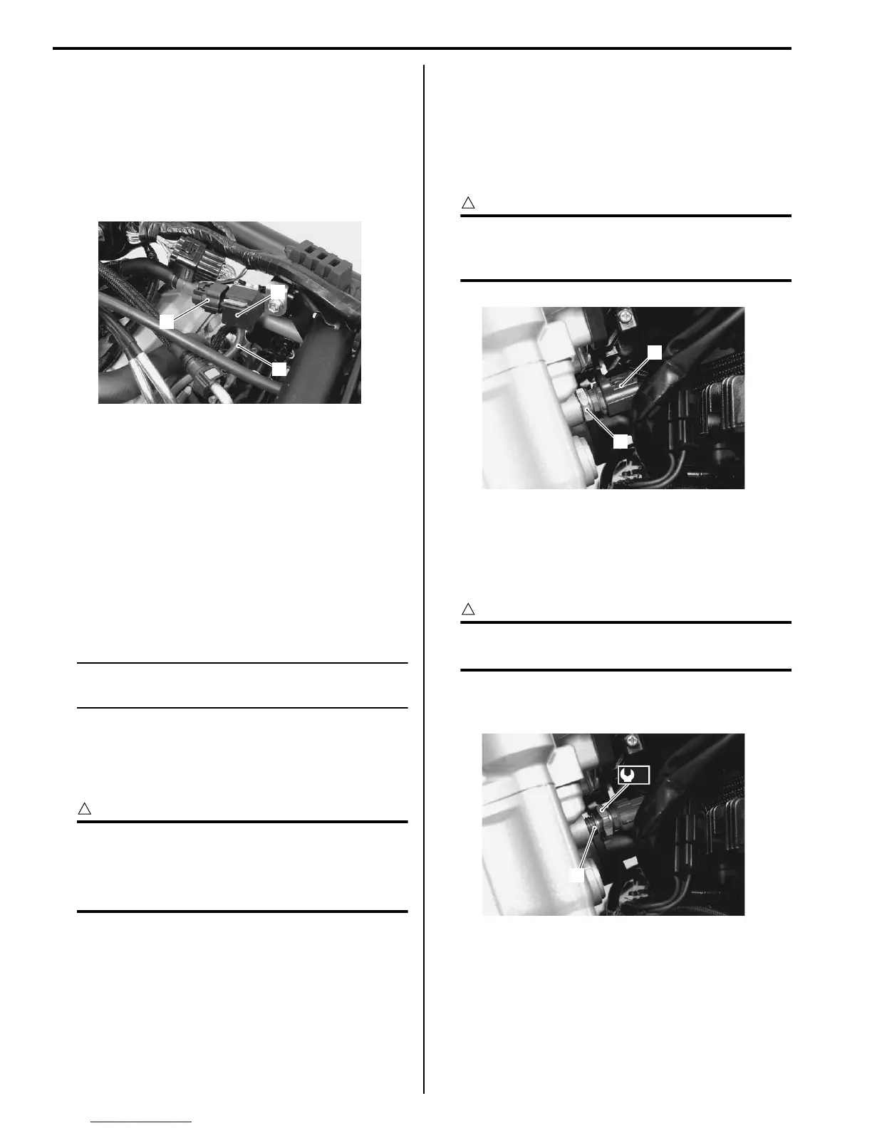
2) Disconnect the IAP sensor (No.1) coupler (1) and
vacuum hose (2).
3) Remove the IAP sensor (No.1) (3).
Installation
Install the IAP sensor (No.1) in the reverse order of
removal.
IAP / TP / IAT Sensor Inspection
B718H11306029
Refer to “DTC “C17” (P1750-H/L): IAP Sensor (No.2)
Circuit Malfunction in Section 1A (Page 1A-52)”, “DTC
“C14” (P0120-H/L): TP Sensor Circuit Malfunction in
Section 1A (Page 1A-37)” and “DTC “C21” (P0110-H/L):
IAT Sensor Circuit Malfunction in Section 1A (Page 1A-
60)”.
NOTE
IAP sensor (No.2)/TP sensor/IAT sensor are
combined into one.
IAP / TP / IAT Sensor Removal and Installation
B718H11306006
Refer to “Throttle Body Disassembly and Assembly in
Section 1D (Page 1D-10)”.
CAUTION
!
• Never remove the IAP/TP/IAT sensor from
the throttle body.
• The IAP/TP/IAT sensor, STVA and throttle
body are available only as an assembly.
ECT Sensor Removal and Installation
B718H11306011
Removal
1) Drain engine coolant. Refer to “Cooling System
Inspection in Section 0B (Page 0B-12)”.
2) Disconnect the coupler (1) and remove the ECT
sensor (2).
CAUTION
!
Take special care when handling the ECT
sensor. It may cause damage if it gets an
excessive impact.
Installation
Install the ECT sensor in the reverse order of removal.
Pay attention to the following points:
• Tighten the ECT sensor to the specified torque.
CAUTION
!
Use the new gasket washer (1) to prevent
engine coolant leakage.
Tightening torque
ECT sensor (a): 18 N·m (1.8 kgf-m, 13.0 lb-ft)
• Pour engine coolant. Refer to “Cooling System
Inspection in Section 0B (Page 0B-12)”.
1
2
3
I718H1130013-01
1
2
I718H1130015-01
1
(a)
I718H1130007-01

 Loading...


