9C-5 Combination Meter / Fuel Meter / Horn:
Combination Meter Inspection
B718H19306004
LED Inspection
Check that the LEDs (FI indicator light, ABS indicator
(GSF1250A/SA only), Oil pressure, Engine coolant
temperature indicator light and Meter panel illumination)
immediately light up when the ignition switch is turned to
ON.
Check that other LEDs (Neutral indicator light, High-
beam indicator light and Turn signal indicator lights) light
up/go off by operating each switch.
If abnormal condition is found, replace the combination
meter unit with a new one after checking its wire
harness/coupler. Refer to “Combination Meter Removal
and Installation (Page 9C-4)”.
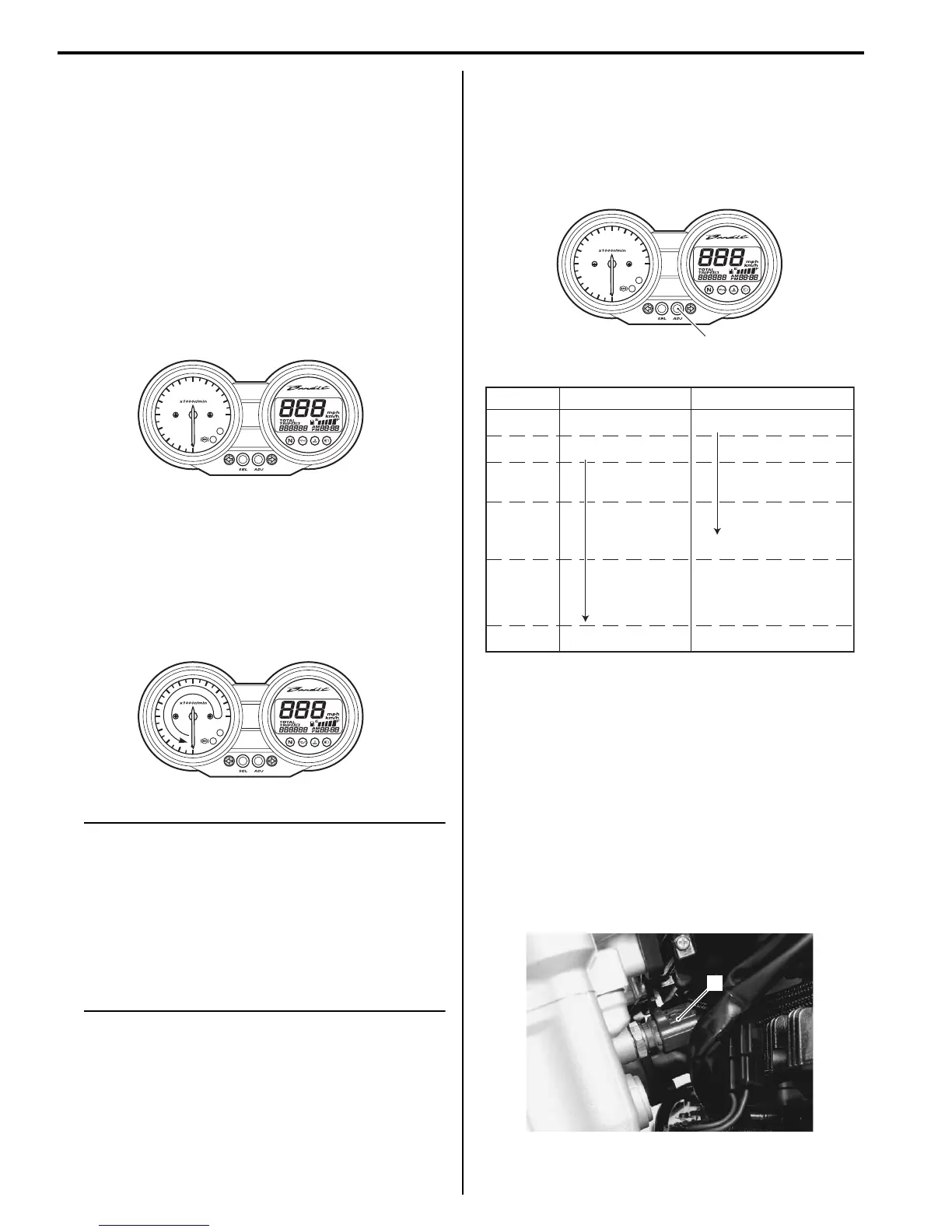
Stepping Motor Inspection and Adjustment
1) Check that the pointer calibrates itself immediately
after turning the ignition switch on and stops at zero
point.
If abnormal condition is found, replace the
combination meter unit with a new one after
checking its wire harness/coupler.
NOTE
• The pointer may not return to the proper
position even turning the ignition switch
on under low temperature condition. In
that case, you can reset the pointer to the
proper position by the following
instruction.
• Complete the operation within 10 seconds
after the ignition switch has been turned
on.
2) With the adjuster switch (1) pressed, turn the ignition
switch on.
3) Release the adjuster switch (1), 3 to 5 seconds after
turning the ignition switch on.
4) Press the adjuster switch (1) twice (within 1 second).
→ Reset
5) Pointer will return to the starting point right after the
completion of the operation. In the case of the
pointer not returning to the proper position after
doing above, replace the combination meter unit.
Refer to “Combination Meter Removal and
Installation (Page 9C-4)”.
Engine Coolant Temperature Indicator Light
Inspection
B718H19306029
Inspect the engine coolant temperature indicator light in
the following procedures:
1) Disconnect the ECT sensor coupler (1).
FI
I718H1930049-01
FI
I718H1930050-01
FI
1
I718H1930051-01
Time Ignition switch Adjuster switch (1)
PUSH
Release
Push
Push→Reset
OFF
ON
0
•
•
•
•
•
•
3 sec.
•
5 sec.
10 sec.
I718H1930006-01
1
I718H1930059-01

 Loading...


