Engine Cooling System: 1F-11
• Connect the water hoses securely. Refer to “Water
Hose Routing Diagram (Page 1F-3)”.
• Pour engine coolant and bleed air from the cooling
circuit. Refer to “Cooling System Inspection in Section
0B (Page 0B-12)”.
Thermostat Inspection
B718H11606025
Inspect the thermostat in the following procedures:
1) Remove the thermostat. Refer to “Thermostat
Connector / Thermostat Removal and Installation
(Page 1F-9)”.
2) Inspect the thermostat pellet for signs of cracking.
3) Test the thermostat at the bench for control action.
CAUTION
!
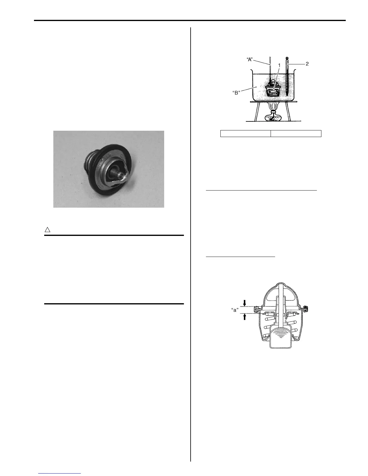
• Do not contact the thermostat (1) and the
column thermometer (2) with a pan.
• As the thermostat operating response to
water temperature change is gradual, do
not raise water temperature too quickly.
• The thermostat with its valve open even
slightly under normal temperature must be
replaced.
4) Immerse the thermostat (1) in the water contained in
a beaker and note that the immersed thermostat is in
suspension.
5) Heat the water by placing the beaker on a stove and
observe the rising temperature on a thermometer
(2).
6) Read the thermometer just when opening the
thermostat. If this reading, which is the temperature
level at which the thermostat valve begins to open, is
out of the standard value, replace the thermostat
with a new one.
Thermostat valve opening temperature
Standard: Approx. 82 °C (180 °F)
7) Keep on heating the water to raise its temperature.
8) Just when the water temperature reaches specified
value, the thermostat valve should have been lifted
by at least 8 mm (0.31 in). A thermostat failing to
satisfy either of the two requirements (start-to-open
temperature and valve lift) must be replaced.
Thermostat valve lift “a”
Standard: 8 mm and over at 95 °C (0.31 in and
over at 203 °F)
9) Install the thermostat. Refer to “Thermostat
Connector / Thermostat Removal and Installation
(Page 1F-9)”.
I718H1160051-01
“A”: String “B”: Water
I705H1160030-03
I705H1160031-04

 Loading...


