Brake Control System and Diagnosis: 4A-8
2) Inspect the switch for continuity with a tester.
If any abnormality is found, replace the front brake
light switch with a new one. Refer to “Front Brake
Master Cylinder / Brake Lever Disassembly and
Assembly (Page 4A-15)”.
Special tool
: 09900–25008 (Multi-circuit tester set)
Tester knob indication
Continuity ( )
3) Connect the front brake light switch lead coupler.
Rear Brake Light Switch Inspection
B718H14106003
Inspect the rear brake light switch in the following
procedures:
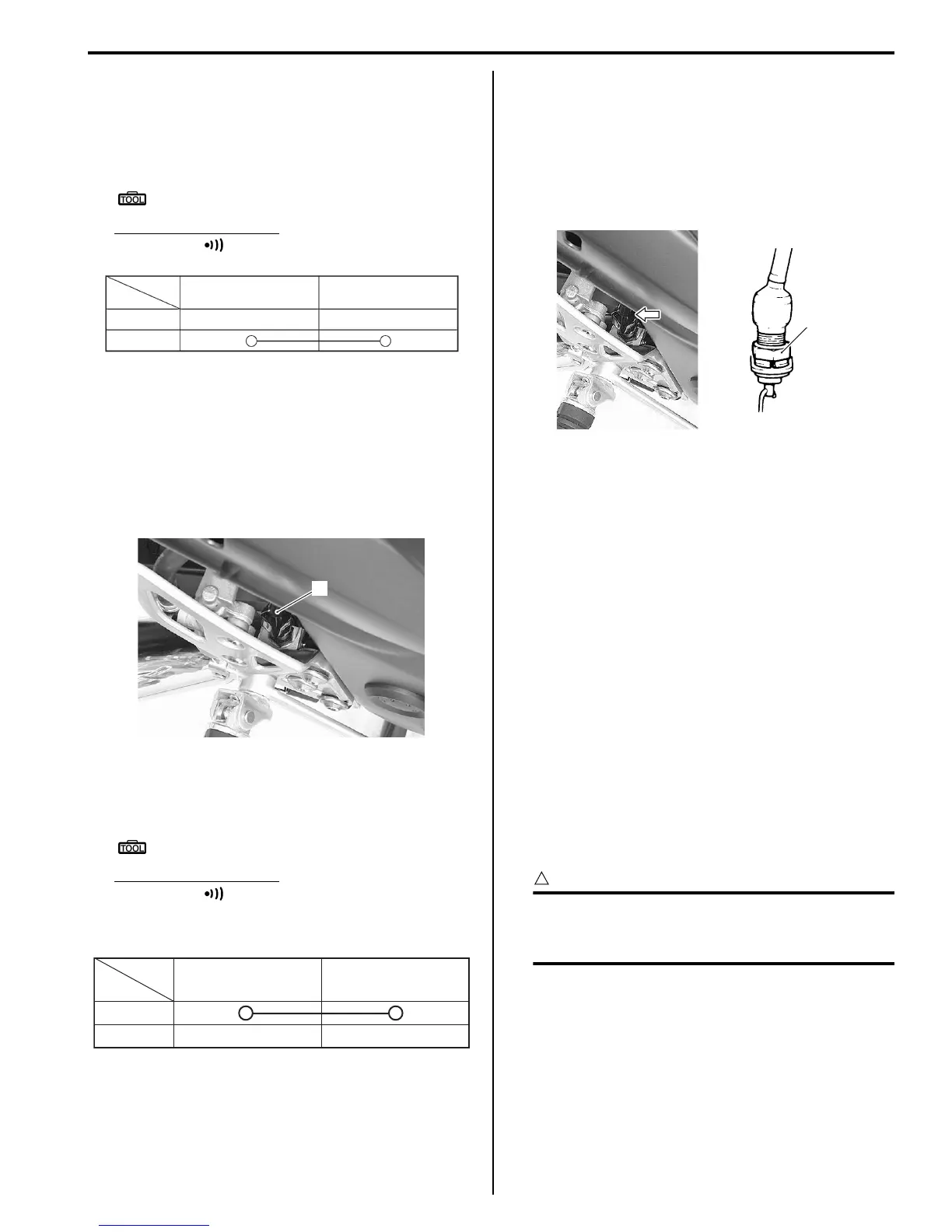
1) Disconnect the rear brake light switch lead coupler
(1).
2) Inspect the switch for continuity with a tester.
If any abnormality is found, replace the rear brake
light switch with a new one.
Special tool
: 09900–25008 (Multi-circuit tester set)
Tester knob indication
Continuity ( )
Rear brake light switch
3) Connect the rear brake light switch lead coupler.
Rear Brake Light Switch Inspection and
Adjustment
B718H14106004
Check the rear brake light switch so that the brake light
will come on just before pressure is felt when the brake
pedal is depressed. If the brake light switch adjustment
is necessary, turn the adjuster nut (1) in or out while
holding the brake pedal.
Brake Fluid Level Check
B718H14106005
Refer to “Brake System Inspection in Section 0B
(Page 0B-17)”.
Brake Hose Inspection
B718H14106006
Refer to “Brake System Inspection in Section 0B
(Page 0B-17)”.
Air Bleeding from Brake Fluid Circuit
B718H14106007
Air trapped in the brake fluid circuit acts like a cushion to
absorb a large proportion of the pressure developed by
the master cylinder and thus interferes with the full
braking performance of the brake caliper. The presence
of air is indicated by “sponginess” of the brake lever and
also by lack of braking force. Considering the danger to
which such trapped air exposes the machine and rider, it
is essential that after remounting the brake and restoring
the brake system to the normal condition, the brake fluid
circuit be purged of air in the following manner:
CAUTION
!
Handle brake fluid with care: the fluid reacts
chemically with paint, plastic, rubber
materials, etc.
Terminal (B/G) Terminal (B)
Color
Position
OFF
ON
I649G1410004-03
1
I718H1410039-02
Color
Position
ON
OFF
Terminal (O/G) Terminal (W/B)
I649G1410006-03
1
I718H1410008-02

 Loading...


