4E-73 ABS:
Installation
Refer to “Wheel Speed Sensor and Sensor Rotor
Inspection (Page 4E-74)”.
Install the front wheel speed sensor rotor in the reverse
order of removal. Pay attention to the following points:
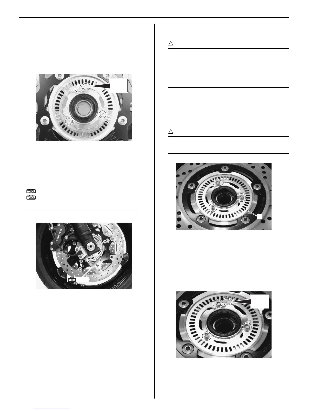
• Install the wheel speed sensor rotor as the letters
“50T” face outside.
• Install the front wheel assembly. Refer to “Front Wheel
Assembly Removal and Installation in Section 2D
(Page 2D-6)”.
• Check the clearance between the front wheel speed
sensor and sensor rotor using the thickness gauge.
Special tool
(A): 09900–20803 (Thickness gauge)
(B): 09900–20806 (Thickness gauge)
Wheel speed sensor – sensor rotor clearance
0.3 – 1.5 mm (0.012 – 0.059 in)
Rear Wheel Speed Sensor Rotor Removal and
Installation
B718H14506007
CAUTION
!
• The ABS is made up of many precision
parts; never subject it to strong impacts or
allow it to become dirty or dusty.
• Do not hit the rear wheel speed sensor
rotor when dismounting the rear wheel.
Removal
1) Remove the rear wheel assembly. Refer to “Rear
Wheel Assembly Removal and Installation in Section
2D (Page 2D-16)”.
2) Remove the rear wheel speed sensor rotor (1).
CAUTION
!
When replacing the tire, make sure not to
damage the sensor rotor.
Installation
Refer to “Wheel Speed Sensor and Sensor Rotor
Inspection (Page 4E-74)”.
Install the rear wheel speed sensor rotor in the reverse
order of removal. Pay attention to the following points:
• Install the wheel speed sensor rotor as the letters
“50T” face outside.
50T
I718H1450105-02
(A), (B)
I718H1450025-01
1
I718H1450106-02
50T
I718H1450107-02

 Loading...


