1A-13 Engine General Information and Diagnosis:
4) Start the engine or crank the engine for more than 4
seconds.
5) Check the DTC to determine the malfunction part.
Refer to “DTC Table (Page 1A-18)”.
NOTE
• Read the DTC (Diagnostic Trouble Code)
and show data when trouble (displaying
data at the time of DTC) according to
instructions displayed on SDS.
• Not only SDS is used for detecting
Diagnostic Trouble Codes but also for
reproducing and checking on screen the
failure condition as described by
customers using the trigger. (Refer to
“Show Data When Trouble (Displaying
Data at the Time of DTC) (Page 1A-14)”.)
• How to use trigger. (Refer to the SDS
operation manual for further details.)
6) After repairing the trouble, clear to delete history
code (Past DTC). Refer to “Use of SDS Diagnosis
Reset Procedures (Page 1A-13)”.
7) Close the SDS tool and turn the ignition switch OFF.
8) Disconnect the SDS tool and install the right frame
cover.
Use of SDS Diagnosis Reset Procedures
B718H11104007
NOTE
The malfunction code is memorized in the
ECM also when the wire coupler of any
sensor is disconnected. Therefore, when a
wire coupler has been disconnected at the
time of diagnosis, erase the stored
malfunction history code using SDS.
1) After repairing the trouble, turn OFF the ignition
switch and turn ON again.
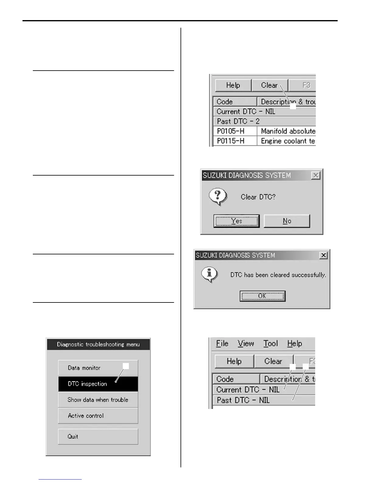
2) Click the DTC inspection button (1).
3) Check the DTC.
4) The previous malfunction history code (Past DTC)
still remains stored in the ECM. Therefore, erase the
history code memorized in the ECM using SDS tool.
5) Click “Clear” (2) to delete history code (Past DTC).
6) Follow the displayed instructions.
7) Check that both “Current DTC” (3) and “Past DTC”
(4) are deleted (NIL).
8) Close the SDS tool and turn the ignition switch OFF.
9) Disconnect the SDS tool and install the right frame
cover.
1
I705H1110003-01
2
I705H1110005-01
I705H1110006-01
I705H1110009-01
3
4
I705H1110008-01

 Loading...


