4A-19 Brake Control System and Diagnosis:
4) Place a rag underneath the brake hose union bolt (2)
on the master cylinder to catch any spilt brake fluid.
5) Remove the brake hose union bolt (2) and
disconnect the brake hose.
6) Loosen the lock-nut (3).
7) Remove the master cylinder mounting bolts (4).
8) Remove the master cylinder along with the reservoir
by turning the push rod (5).
Installation
Install the rear brake master cylinder in the reverse order
of removal. Pay attention to the following points:
CAUTION
!
The seal washers should be replaced with the
new ones to prevent fluid leakage.
• Tighten the master cylinder mounting bolts (1) to the
specified torque.
• Tighten the lock-nut (2) to the specified torque.
• After setting the brake hose union to the stopper,
tighten the union bolt (3) to the specified torque.
Tightening torque
Rear master cylinder mounting bolt (a): 23 N·m (
2.3 kgf-m, 16.5 lb-ft)
Rear master cylinder rod lock-nut (b): 18 N·m (1.8
kgf-m, 13.0 lb-ft)
Brake hose union bolt (c): 23 N·m (2.3 kgf-m, 16.5
lb-ft)
• Bleed air from the system after reassembling the
master cylinder. Refer to “Air Bleeding from Brake
Fluid Circuit (Page 4A-8)”.
• Adjust the brake pedal height. Refer to “Brake System
Inspection in Section 0B (Page 0B-17)”.
Rear Brake Master Cylinder Disassembly and
Assembly
B718H14106017
Refer to “Front Brake Master Cylinder Assembly
Removal and Installation (Page 4A-14)”.
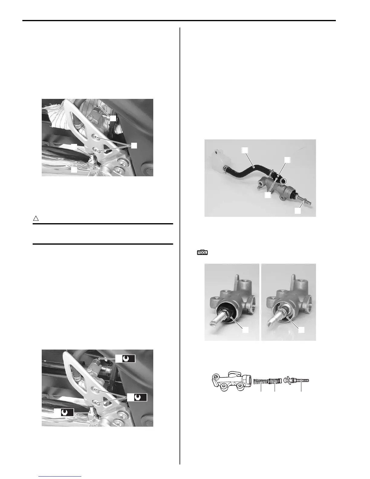
Disassembly
1) Disconnect the reservoir hose (1).
2) Remove the lock-nut (2).
3) Remove the brake hose connector (3) and O-ring
(4).
4) Pull out the dust boot (5) and remove the snap ring
(6).
Special tool
: 09900–06108 (Snap ring pliers)
5) Remove the push rod (7), piston/cup set (8) and
spring (9).
2
4
3
5
I718H1410057-01
(a)
1
(c)
3
(b)
2
I718H1410058-01
1
3
4
2
I718H1410059-04
5
6
I718H1410060-01
7
8
9
I649G1410035-02

 Loading...


