Combination Meter / Fuel Meter / Horn: 9C-8
Fuel Level Gauge Inspection
B718H19306006
Inspect the fuel level gauge in the following procedures:
1) Remove the fuel level gauge. Refer to “Fuel Pump
Assembly / Fuel Level Gauge Removal and
Installation in Section 1G (Page 1G-11)”.
2) Measure the resistance at each fuel level gauge in
float position. If the resistance is incorrect, replace
fuel level gauge with a new one.
Special tool
: 09900–25008 (Multi-circuit tester set)
Tester knob indication
Resistance (Ω)
3) Install the fuel level gauge. Refer to “Fuel Pump
Assembly / Fuel Level Gauge Removal and
Installation in Section 1G (Page 1G-11)”.
Speedometer Inspection
B718H19306020
If the speedometer, odometer or tripmeter does not
function properly, inspect the speed sensor and the
coupler connections. If the speed sensor and coupler
connections are OK, replace the combination meter unit
with a new one. Refer to “Combination Meter Removal
and Installation (Page 9C-4)”.
Speed Sensor Removal and Installation
B718H19306021
Removal
1) Remove the seat. Refer to “Exterior Parts Removal
and Installation in Section 9D (Page 9D-6)”.
2) Remove the left frame cover. Refer to “Exterior Parts
Removal and Installation in Section 9D (Page 9D-
6)”.
3) Remove the engine sprocket outer cover. Refer to
“Engine Sprocket Removal and Installation in
Section 3A (Page 3A-2)”.
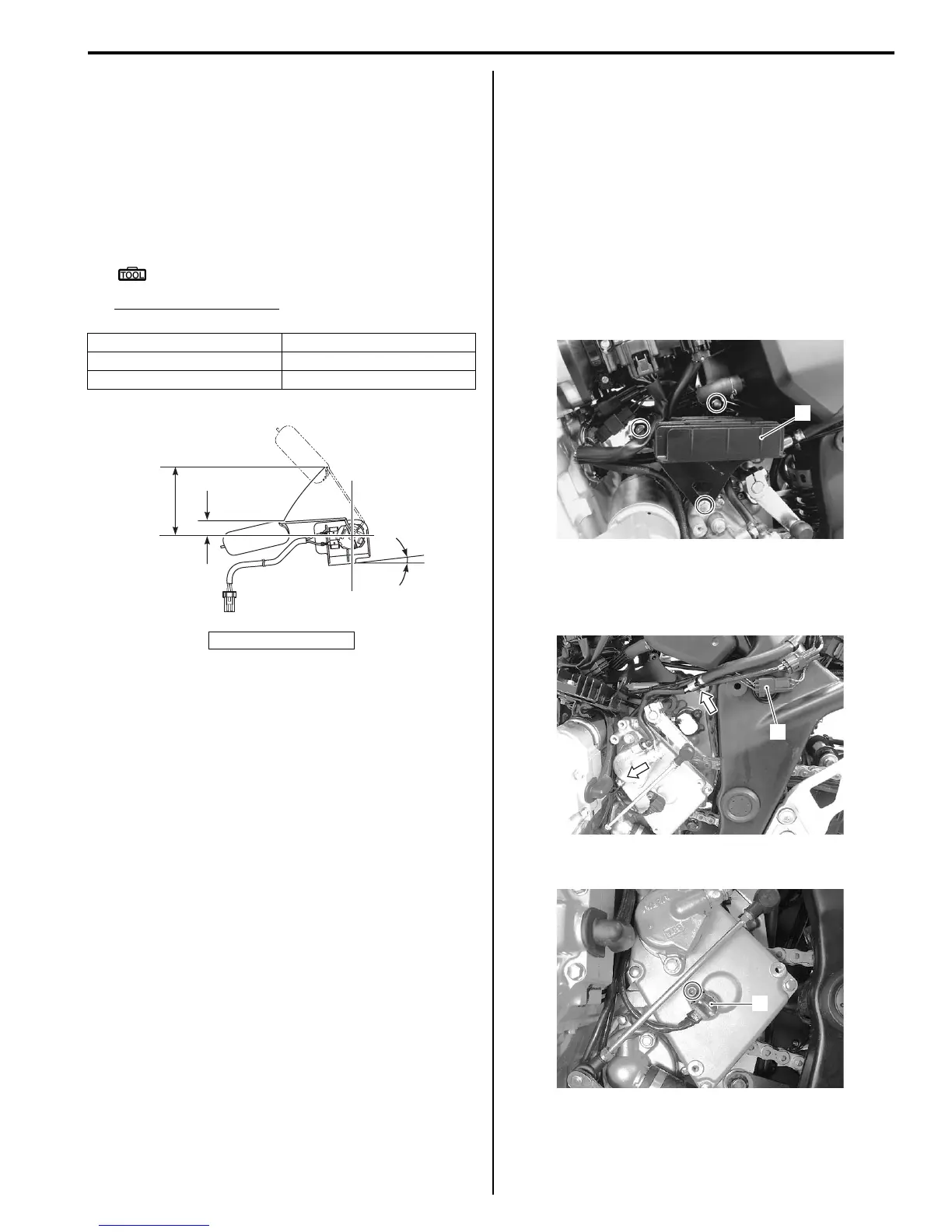
4) Move the regulator/rectifier assembly (1) by
removing the regulator/rectifier bracket bolts.
5) Disconnect the speed sensor coupler (2).
6) Release the speed sensor lead wire from the
clamps.
7) Remove the speed sensor (3).
Float position Resistance
Full “a” Approx. 10 Ω
Empty “b” Approx. 216 Ω
“A”: Horizontal
“a”
“b”
“A”
14.4 mm
(0.57 in.)
73.5 mm
(2.89 in.)
15˚
“A”
I718H1930061-01
1
I718H1930056-01
2
I718H1930025-02
3
I718H1930024-03

 Loading...


