5B-12 Manual Transmission:
Transmission Related Parts Inspection
B718H15206007
Refer to “Transmission Removal (Page 5B-3)”,
“Transmission Installation (Page 5B-5)” and
“Countershaft Gear / Driveshaft Gear Disassembly and
Assembly (Page 5B-9)”.
Gearshift Fork to Groove Clearance
NOTE
The clearance for each gearshift fork plays
an important role in the smoothness and
positiveness of the shifting action.
Using a thickness gauge, check the gearshift fork
clearance in the groove of its gear.
If the clearance checked is noted to exceed the limit
specified, replace the fork or its gear, or both.
Special tool
(A): 09900–20803 (Thickness gauge)
Gearshift fork to gearshift fork groove clearance
Standard: 0.1 – 0.3 mm (0.004 – 0.012 in)
Service limit: 0.5 mm (0.02 in)
Gearshift Fork Groove Width
Measure the gearshift fork groove width using the
vernier calipers.
Special tool
(A): 09900–20102 (Vernier calipers (1/20 mm,
200 mm))
Gearshift fork groove width
Standard: 5.0 – 5.1 mm (0.197 – 0.201 in)
Gearshift Fork Thickness
Measure the gearshift fork thickness using the vernier
calipers.
Special tool
(A): 09900–20102 (Vernier calipers (1/20 mm,
200 mm))
Gearshift fork thickness
Standard: 4.8 – 4.9 mm (0.189 – 0.193 in)
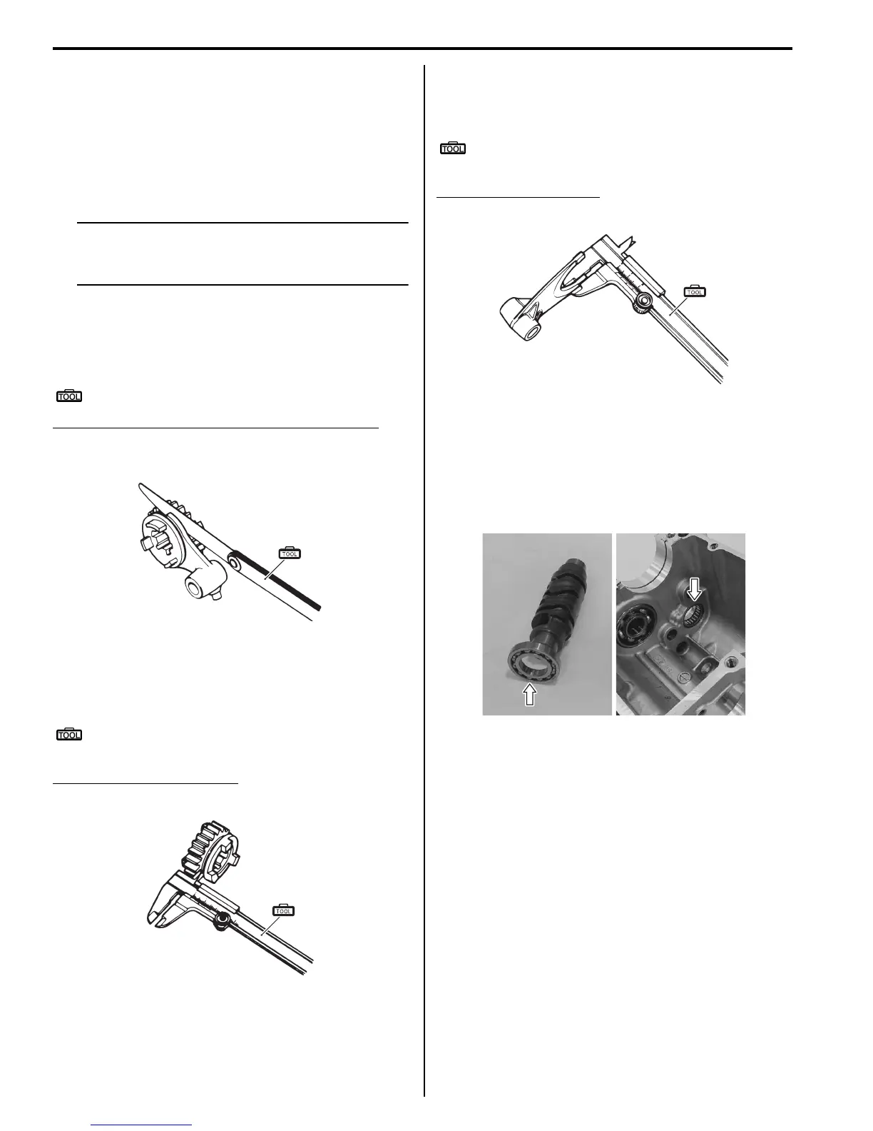
Gearshift Cam Bearing
Inspect the gearshift cam bearings, left and right for
abnormal noise and smooth rotation.
Replace the bearing if there is anything unusual. Refer
to “Transmission Removal (Page 5B-3)” and
“Transmission Installation (Page 5B-5)”.
Gear Position (GP) Switch Inspection
B718H15206008
Refer to “Side-stand / Ignition Interlock System Parts
Inspection in Section 1I (Page 1I-8)”.
Gear Position (GP) Switch Removal and
Installation
B718H15206009
Removal
1) Turn the ignition switch OFF.
2) Remove the left flame cover. Refer to “Exterior Parts
Removal and Installation in Section 9D (Page 9D-
6)”.
3) Remove the engine sprocket outer cover. Refer to
“Engine Sprocket Removal and Installation in
Section 3A (Page 3A-2)”.
(A)
I649G1520056-03
(A)
I649G1520057-03
(A)
I649G1520058-03
I718H1520041-01

 Loading...


