1D-36 Engine Mechanical:
Valve Clearance Inspection and Adjustment
B718H11406008
Refer to “Valve Clearance Inspection and Adjustment in
Section 0B (Page 0B-5)”.
Camshaft Inspection
B718H11406009
Refer to “Engine Top Side Disassembly (Page 1D-24)”.
Refer to “Engine Top Side Assembly (Page 1D-28)”.
Camshaft Identification
The exhaust camshaft has the embossed letters “EX”
and the intake camshaft has the embossed letters “IN”.
Cam Wear
Check the camshaft for wear or damage.
Measure the cam height “a” with a micrometer.
Replace a camshaft if the cams are worn to the service
limit.
Special tool
: 09900–20202 (Micrometer (1/100 mm, 25 – 50
mm))
Cam height “a”
Service limit: (IN) 34.98 mm (1.377 in)
Service limit: (EX) 33.88 mm (1.334 in)
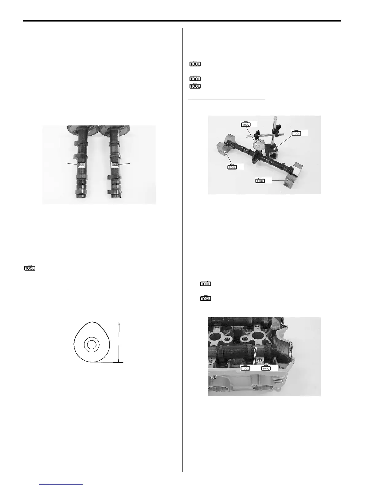
Camshaft Runout
Measure the runout using the dial gauge. Replace the
camshaft if the runout exceeds the limit.
Special tool
(A): 09900–20607 (Dial gauge (1/100 mm, 10
mm))
(B): 09900–20701 (Magnetic stand)
(C): 09900–21304 (V-block (100 mm))
Camshaft runout (IN & EX)
Service limit: 0.10 mm (0.004 in)
Camshaft Journal Wear
Inspect the camshaft journal wear in the following
procedures:
1) Determine whether or not each journal is worn down
to the limit by measuring the oil clearance with the
camshaft installed in place.
2) Use the plastigauge to read the clearance at the
widest portion, which is specified as follows.
Special tool
(A): 09900–22301 (Plastigauge (0.025 -
0.076 mm))
(B): 09900–22302 (Plastigauge (0.051 -
0.152 mm))
EX
IN
I718H1140081-01
“a”
I649G1140199-02
(A)
(B)
(C)
(C)
I718H1140082-01
(A) (B)
/
I718H1140083-03

 Loading...


