Ignition System: 1H-8
3) Measure the CKP sensor peak voltage in the
following procedure.
a) Shift the transmission into neutral, turn the
ignition switch ON and grasp the clutch lever.
b) Press the starter button and allow the engine to
crank for a few seconds, and then measure the
CKP sensor peak voltage.
4) Repeat the b) procedure several times and measure
the highest CKP sensor peak voltage.
CKP sensor peak voltage
2.0 V and more (BI/Y – Green)
5) If the peak voltage is within the specification, check
the continuity between the CKP sensor coupler and
ECM coupler.
CAUTION
!
Normally, use the needle pointed probe to the
backside of the lead wire coupler to prevent
the terminal bend and terminal alignment.
6) After measuring the CKP sensor peak voltage,
connect the CKP sensor coupler.
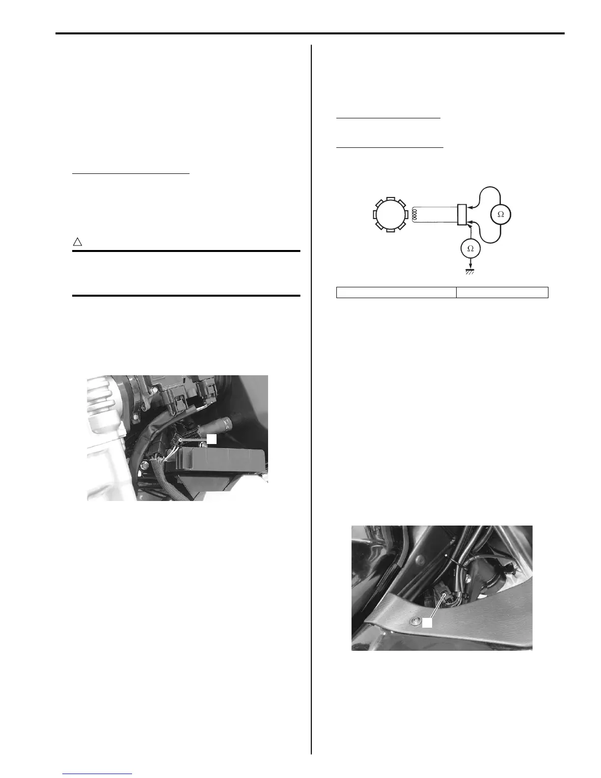
CKP Sensor Resistance
1) Disconnect the CKP sensor coupler (1).
2) Measure the resistance between the lead wires and
ground. If the resistance is not within the standard
range, replace the CKP sensor with a new one.
Refer to “CKP Sensor Removal and Installation
(Page 1H-8)”.
Tester knob indication
Resistance (Ω)
CKP sensor resistance
90 – 150 Ω (Bl/Y – Green)
∞ Ω (Bl/Y – Ground)
3) After measuring the CKP sensor resistance, connect
the CKP sensor coupler.
CKP Sensor Removal and Installation
B718H11806009
Refer to “Generator Removal and Installation in Section
1J (Page 1J-4)”.
Engine Stop Switch Inspection
B718H11806010
Inspect the engine stop switch in the following
procedures:
1) Turn the ignition switch OFF.
2) Remove the right frame head cover. (GSF1250/A)
Refer to “Exterior Parts Removal and Installation in
Section 9D (Page 9D-6)”.
3) Disconnect the right handlebar switch coupler (1).
1
I718H1180026-01
2. CKP sensor coupler 3. CKP sensor
3
2
I718H1180008-02
1
I718H1180017-01

 Loading...


