1D-48 Engine Mechanical:
8) After installing the valve guides, refinish their guiding
bores using the reamer. Be sure to clean and oil the
guides after reaming.
NOTE
• Be sure to cool down the cylinder head to
ambient air temperature.
• Insert the reamer from the combustion
chamber and always turn the reamer
handle clockwise.
Special tool
(C): 09916–34542 (Reamer handle)
(E): 09916–33210 (Valve guide reamer (4.5
mm))
9) Reassemble the cylinder head. Refer to “Cylinder
Head Disassembly and Assembly (Page 1D-40)”.
10) Install the cylinder head assembly. Refer to “Engine
Top Side Assembly (Page 1D-28)”.
Valve Seat Repair
B718H11406019
The valve seats (1) for both the intake and exhaust
valves are machined to three different angles. The seat
contact surface is cut at 45°.
CAUTION
!
• The valve seat contact area must be
inspected after each cut.
• Do not use lapping compound after the
final cut is made. The finished valve seat
should have a velvety smooth finish but
not a highly polished or shiny finish. This
will provide a soft surface for the final
seating of the valve which will occur
during the first few seconds of engine
operation.
NOTE
After servicing the valve seats, be sure to
check the valve clearance after the cylinder
head has been reinstalled. Refer to “Valve
Clearance Inspection and Adjustment in
Section 0B (Page 0B-5)”.
Cylinder Disassembly and Assembly
B718H11406031
Refer to “Engine Top Side Disassembly (Page 1D-24)”.
Refer to “Engine Top Side Assembly (Page 1D-28)”.
Disassembly
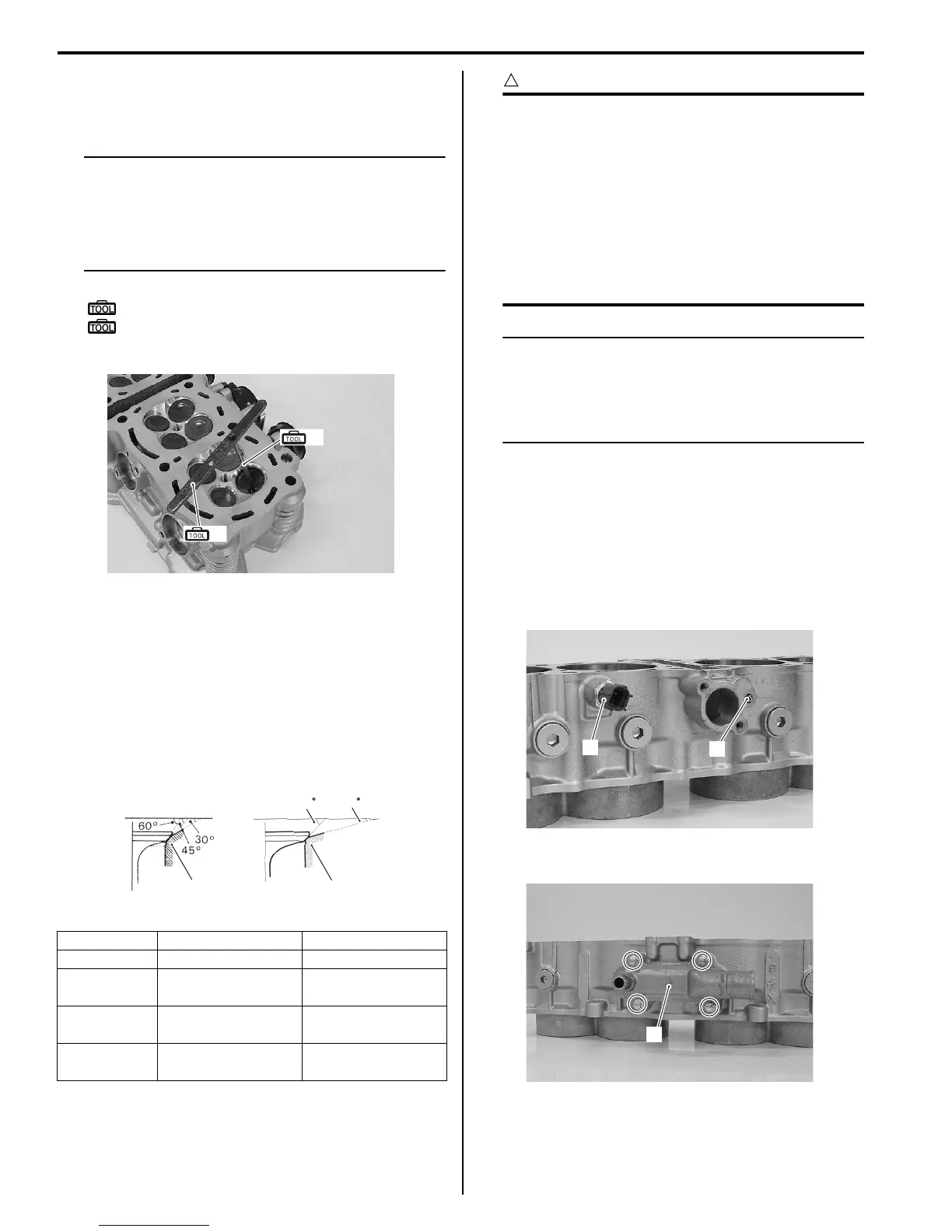
1) Remove the ECT sensor (1) and oil jet (for cam
chain tension adjuster) (2).
2) Remove the water inlet connector (3).
Intake Exhaust
Seat angle 15°/45°/60° 15°/45°
Seat width
0.9 – 1.1 mm
(0.035 – 0.043 in)
←
Valve
diameter
31 mm
(1.22 in)
27 mm
(1.06 in)
Valve guide
I.D.
4.500 – 4.512 mm
(0.1772 – 0.1776 in)
←
(E)
(C)
I718H1140129-01
1
1
45 15
IN. EX.
I718H1140130-01
1
2
I718H1140131-01
3
I718H1140132-01

 Loading...


