1A-11 Engine General Information and Diagnosis:
Self-Diagnostic Procedures
B718H11104005
Use of Mode Select Switch
NOTE
• Do not disconnect coupler from ECM, the
battery cable from the battery, ECM ground
wire harness from the engine or main fuse
before confirming DTC (Diagnostic Trouble
Code) stored in memory. Such
disconnection will erase memorized
information in ECM memory.
• DTC stored in ECM memory can be
checked by the special tool.
• Before checking DTC, read self-diagnosis
function “User mode and dealer mode”
(Refer to “Self-Diagnosis Function
(Page 1A-2)”.) carefully to have good
understanding as to what functions are
available and how to use it.
• Be sure to read “Precautions for Electrical
Circuit Service” (Refer to “Precautions for
Electrical Circuit Service in Section 00
(Page 00-2)”.) before inspection and
observe what is written there.
1) Remove the right frame cover. Refer to “Exterior
Parts Removal and Installation in Section 9D
(Page 9D-6)”.
2) Connect the special tool to the mode select switch at
the wiring harness.
Special tool
(A): 09930–82720 (Mode select switch)
3) Start the engine or crank the engine for more than 4
seconds.
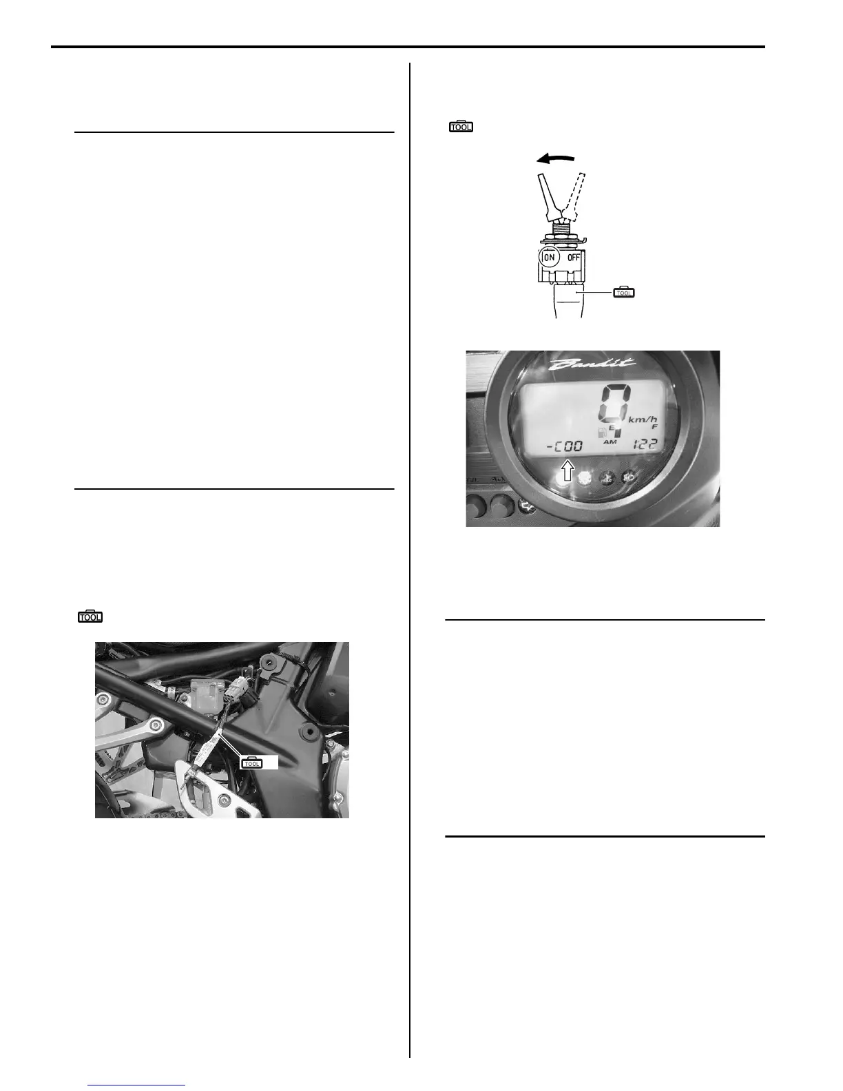
4) Turn the special tool’s switch ON.
5) Check the DTC to determine the malfunction part.
Refer to “DTC Table (Page 1A-18)”.
Special tool
(A): 09930–82720 (Mode select switch)
6) After repairing the trouble, turn OFF the ignition
switch and turn ON again. If DTC is indicated (C00),
the malfunction is cleared.
NOTE
• Even though DTC (C00) is indicated, the
previous malfunction history DTC still
remains stored in the ECM. Therefore,
erase the history DTC memorized in the
ECM using SDS.
• DTC is memorized in the ECM also when
the wire coupler of any sensor is
disconnected. Therefore, when a wire
coupler has been disconnected at the time
of diagnosis, erase the stored history DTC
using SDS. Refer to “Use of SDS Diagnosis
Reset Procedures (Page 1A-13)”.
7) Turn the ignition switch OFF and disconnect the
special tool from the mode select switch.
8) Reinstall the right frame cover.
(A)
I718H1110145-02
(A)
I718H1110006-04
I718H1110144-01

 Loading...


