1H-9 Ignition System:
4) Inspect the engine stop switch for continuity with a
tester.
If any abnormality is found, replace the right
handlebar switch assembly with a new one. Refer to
“Handlebar Removal and Installation in Section 6B
(Page 6B-3)”.
Special tool
: 09900–25008 (Multi-circuit tester set)
Tester knob indication
Continuity ( )
5) After finishing the engine stop switch inspection,
reinstall the removed parts.
Ignition Switch Inspection
B718H11806011
Refer to “Ignition Switch Inspection in Section 9C
(Page 9C-10)”.
Ignition Switch Removal and Installation
B718H11806015
Removal
1) Support the motorcycle with the center stand.
2) Remove the right frame head cover. (GSF1250/A)
Refer to “Exterior Parts Removal and Installation in
Section 9D (Page 9D-6)”.
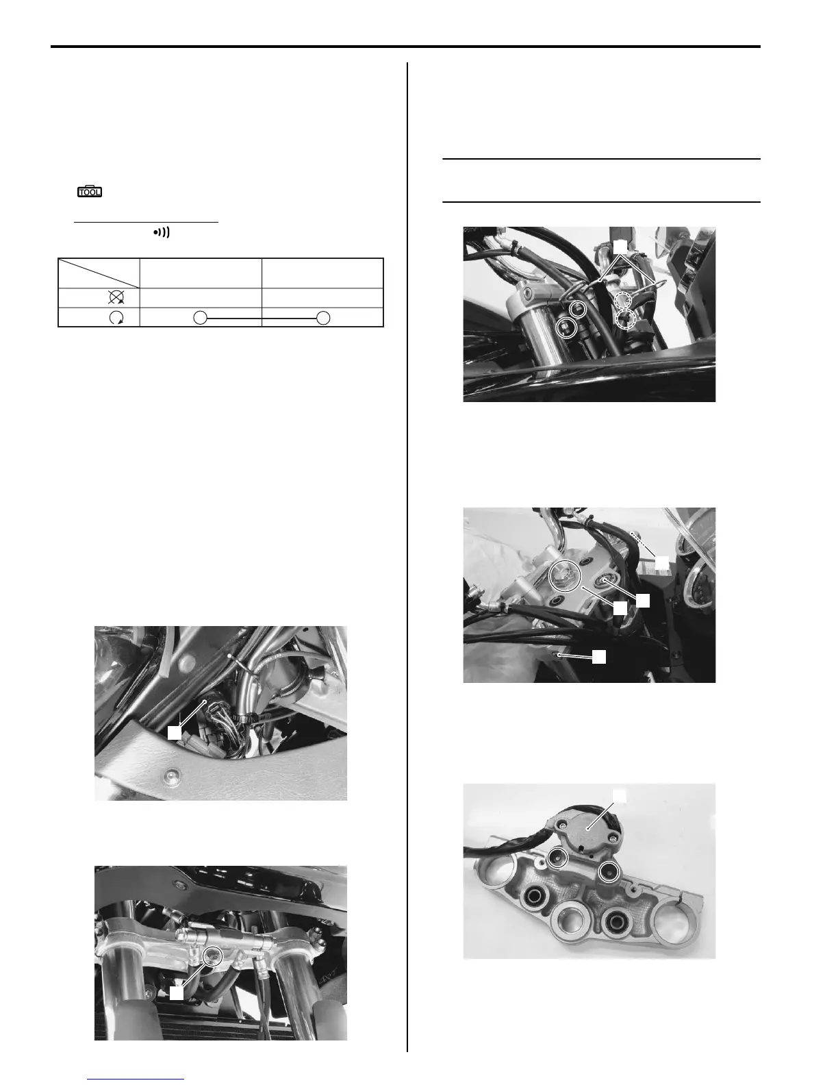
3) Disconnect the ignition switch coupler (1) and clamp.
4) Remove the brake hose clamp bolt (GSF1250/S) or
brake hose joint bolt (2) (GSF1250A/SA).
5) Remove the combination meter bracket bolts
(GSF1250/A) or cable guides (3) (GSF1250S/SA).
6) Dismount the handlebars by removing the handlebar
holder set nuts.
NOTE
Place a rag on the fuel tank to prevent the
fuel tank scratched.
7) Loosen the front fork upper clamp bolts (4).
8) Remove the steering stem head nut and washer.
9) Remove the steering stem upper bracket (5) along
with the ignition switch (6).
10) Using a center punch, remove the ignition switch
mounting bolts.
11) Remove the ignition switch (6) from the upper
bracket.
B/BI B/R
Color
Position
OFF
RUN
()
()
I649G1180022-02
1
I718H1180018-01
2
I718H1180019-01
3
I718H1180020-03
5
6
4
4
I718H1180021-03
6
I718H1180022-01

 Loading...


