Drive Chain / Drive Train / Drive Shaft: 3A-7
4) Install the rear sprocket mounting drum.
5) Install the rear sprocket mounting drum assembly to
rear wheel hub. Refer to “Rear Sprocket / Rear
Sprocket Mounting Drum Removal and Installation
(Page 3A-4)”.
6) Install the rear wheel assembly. Refer to “Rear
Wheel Assembly Removal and Installation in Section
2D (Page 2D-16)”.
Drive Chain Replacement
B718H13106006
Use the special tool in the following procedures, to cut
and rejoin the drive chain.
NOTE
When using the special tool, apply a small
quantity of grease to the threaded parts of
the special tool.
Special tool
: 09922–22711 (Drive chain cutting and joining
tool)
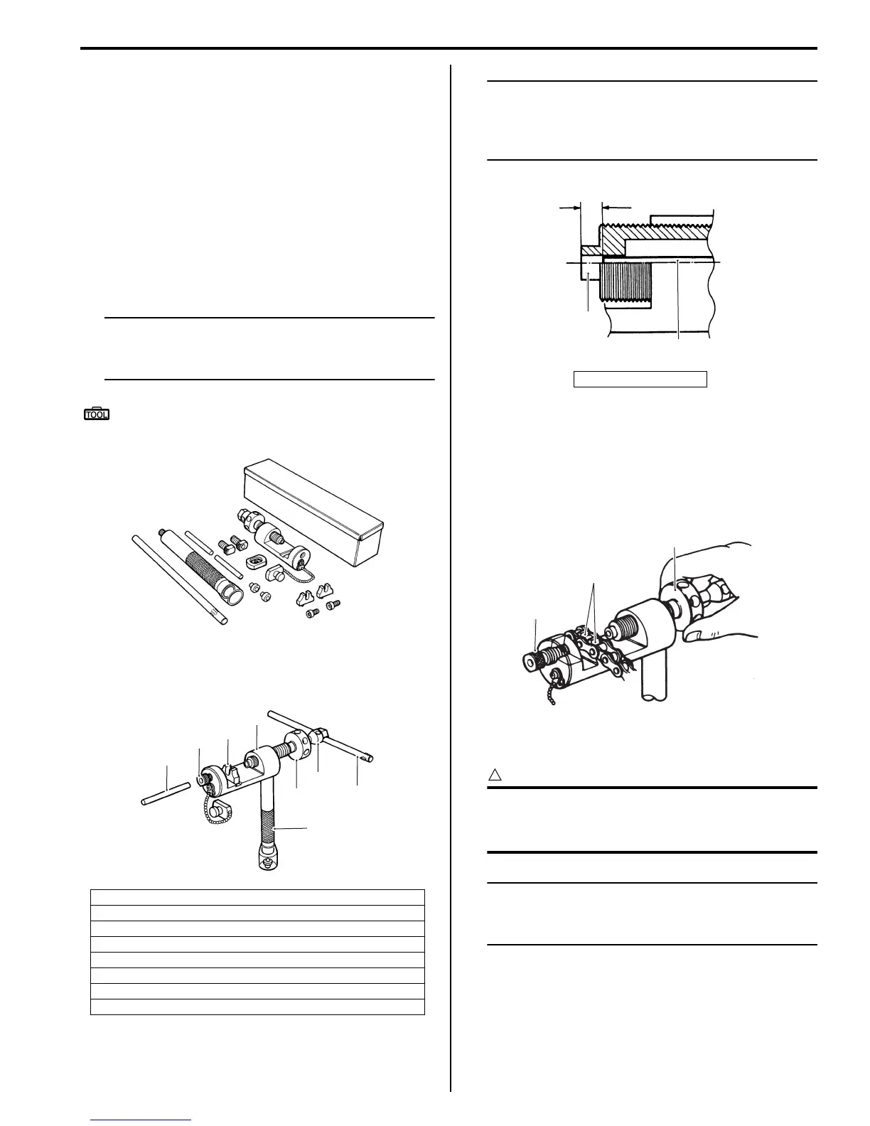
Drive Chain Cutting
1) Set up the special tool as shown in the illustration.
NOTE
The tip of pin remover (1) should be
positioned inside “a” approximately 5 mm
(0.2 in) from the end face of pressure bolt [A]
(2) as shown in the illustration.
2) Place the drive chain link being disjointed on the
holder part (8) of the tool.
3) Turn in both the adjuster bolt (6) and pressure bolt
[A] (3) so that each of their end hole fits over the
chain joint pin properly.
4) Tighten the pressure bolt [A] (3) with the bar.
5) Turn in the pressure bolt [B] (4) with the bar (5) and
force out the drive chain joint pin (9).
CAUTION
!
Continue turning in the pressure bolt [B] (4)
until the joint pin should been completely
pushed out of the chain.
NOTE
After the joint pin (9) is removed, loosen the
pressure bolt [B] (4) and then pressure bolt
[A] (3).
1. Tool body
2. Grip handle
3. Pressure bolt [A]
4. Pressure bolt [B]
5. Bar
6. Adjuster bolt (With through hole)
7. Pin remover
8. Chain holder (Engraved mark 500) with reamer bolt M5 x 10
I649G1310023-02
1
2
3
4
5
6
7
8
I649G1310024-02
“a”: 5 mm (0.2 in)
1
2
“a”
I649G1310025-02
3
6
8
I718H1310032-01

 Loading...


