EasyManuals Logo

Suzuki GSF1250 Service Manual

Suzuki GSF1250
685 pages
To Next Page IconTo Next Page
To Previous Page IconTo Previous Page
Page #471 background imageLoading...
Page #471 background image
Brake Control System and Diagnosis: 4A-18
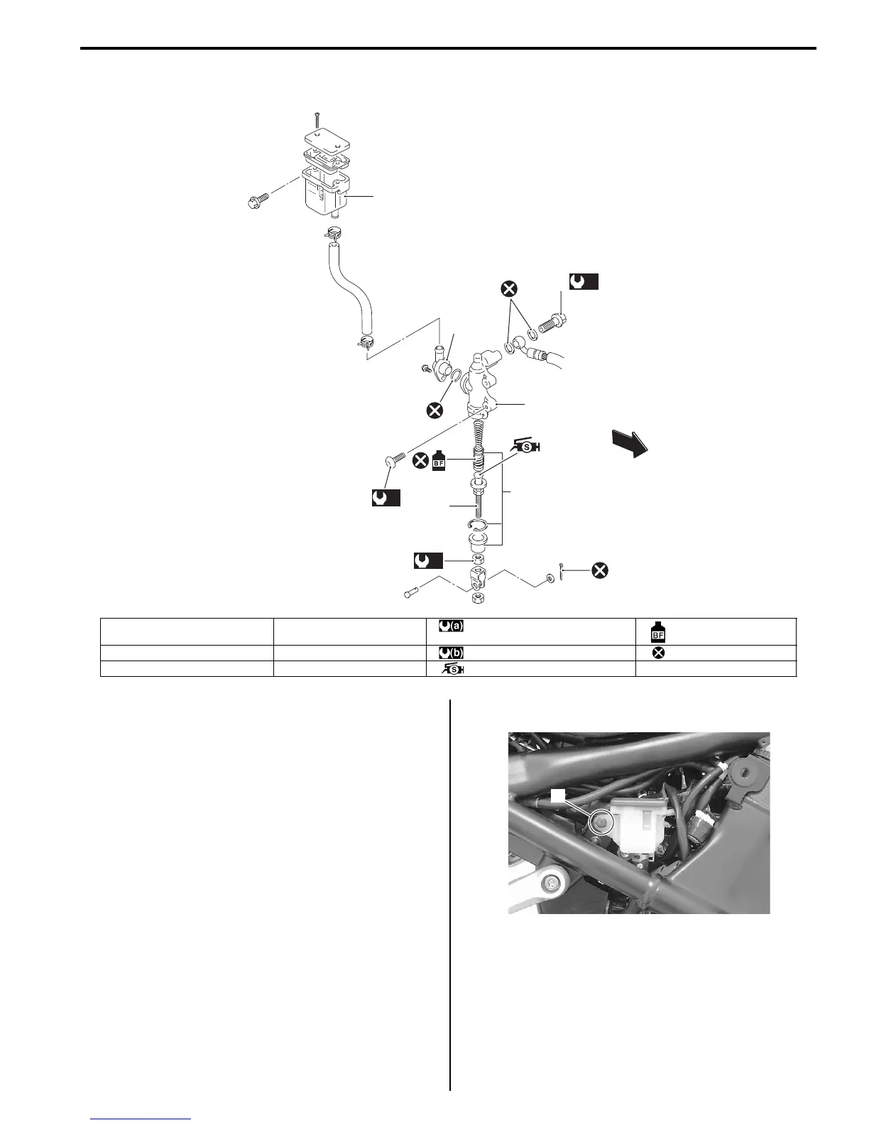
Rear Brake Master Cylinder Components
B718H14106015
Rear Brake Master Cylinder Assembly Removal
and Installation
B718H14106016
Removal
1) Remove the right frame cover. Refer to “Exterior
Parts Removal and Installation in Section 9D
(Page 9D-6)”.
2) Drain brake fluid. Refer to “Brake Fluid Replacement
(Page 4A-10)”.
3) Remove the reservoir mounting bolt (1).
1
3
(a)
2,
4
6
(a)
(b)
5
FWD
FWD
I649G1410029-06
1. Reservoir tank 4. Master cylinder : 23 Nm (2.3 kgf-m, 16.5 lb-ft) : Apply brake fluid.
2. Brake hose union bolt 5. Piston/Cup set : 18 Nm (1.8 kgf-m, 13.0 lb-ft) : Do not reuse.
3. Brake hose connector 6. Push rod : Apply silicone grease.
1
I718H1410056-01

Table of Contents

Other manuals for Suzuki GSF1250

Questions and Answers:

Question and Answer IconNeed help?

Do you have a question about the Suzuki GSF1250 and is the answer not in the manual?

Suzuki GSF1250 Specifications

General IconGeneral
Displacement1255 cc
Bore x Stroke79.0 mm x 64.0 mm
Compression Ratio10.5:1
Fuel SystemFuel injection
Transmission6-speed, constant mesh
Front SuspensionTelescopic, coil spring, oil damped
Rear SuspensionLink type, coil spring, oil damped
Front BrakesDual hydraulic disc
Rear BrakesSingle hydraulic disc
Front Tire120/70ZR17M/C (58W), tubeless
Rear Tire180/55ZR17M/C (73W), tubeless
Overall Length2130 mm
Overall Width790 mm
Seat Height805 mm
Wheelbase1485 mm
Fuel Tank Capacity19.0 L
StarterElectric
Final DriveChain
IgnitionElectronic ignition (transistorized)
Engine Type4-stroke, liquid-cooled, DOHC
Ground Clearance135 mm

Related product manuals