1G-5 Fuel System:
Repair Instructions
Fuel Pressure Inspection
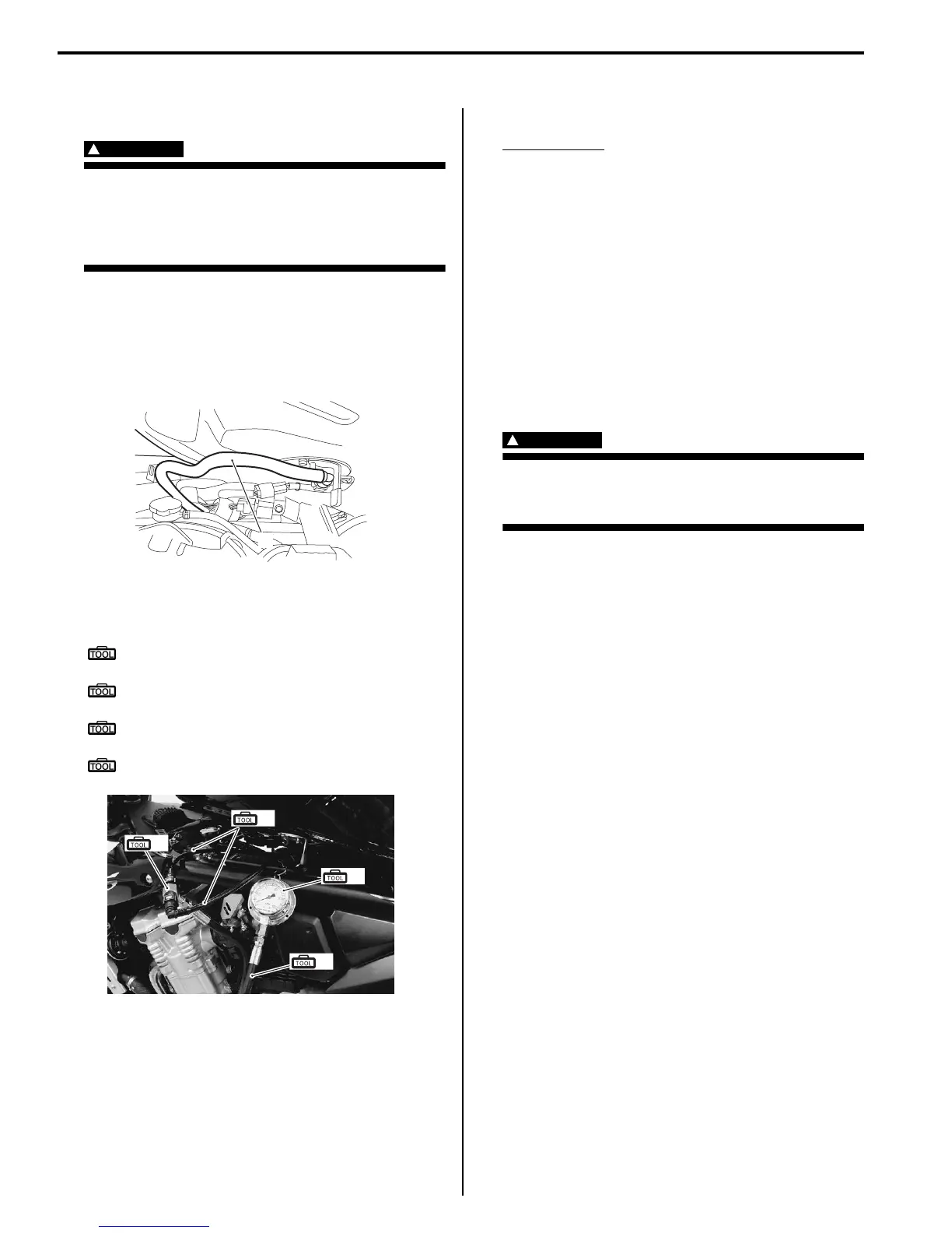
B718H11706042
WARNING
!
• Keep away from fire or spark.
• Spilled gasoline should be wiped off
immediately.
• Work in a well-ventilated area.
Inspect the fuel pressure in the following procedures:
1) Lift and support the fuel tank. Refer to “Fuel Tank
Removal and Installation (Page 1G-9)”.
2) Place a rag under the fuel feed hose and disconnect
fuel feed hose (1) from the fuel pump.
3) Install the special tools between the fuel pump and
fuel delivery pipe.
Special tool
(A): 09940–40211 (Fuel pressure gauge
adapter)
(B): 09940–40220 (Fuel pressure gauge
hose attachment)
(C): 09915–77331 (Meter (for high
pressure))
(D): 09915–74521 (Oil pressure gauge hose)
4) Turn the ignition ON and check for fuel pressure.
Fuel pressure
Approx. 300 kPa (3.0 kgf/cm
2
, 43.5 psi)
If the fuel pressure is lower than the specification,
check for the followings:
• Fuel hose leakage
• Clogged fuel filter
• Pressure regulator
• Fuel pump
If the fuel pressure is higher than the specification,
check for the followings:
• Fuel pump
• Pressure regulator
5) Remove the special tools.
WARNING
!
Before removing the special tools, turn the
ignition switch OFF and release the fuel
pressure slowly.
6) Reinstall the fuel tank. Refer to “Fuel Tank Removal
and Installation (Page 1G-9)”.
Fuel Pump Inspection
B718H11706027
Turn the ignition switch ON and check that the fuel pump
operates for a few seconds.
If the fuel pump motor does not make operating sound,
inspect the fuel pump circuit connections or inspect the
fuel pump relay and TO sensor. Refer to “Fuel Pump
Relay Inspection (Page 1G-7)” and “DTC “C23” (P1651-
H/L): TO Sensor Circuit Malfunction in Section 1A
(Page 1A-67)”.
If the fuel pump relay, TO sensor and fuel pump circuit
connections are OK, the fuel pump may be faulty,
replace the fuel pump with a new one. Refer to “Fuel
Pump Assembly / Fuel Level Gauge Removal and
Installation (Page 1G-11)”.
1
I718H1170017-04
(A)
(B)
(C)
(D)
I718H1170018-01

 Loading...


