Combination Meter / Fuel Meter / Horn: 9C-10
2) Turn the ignition switch ON.
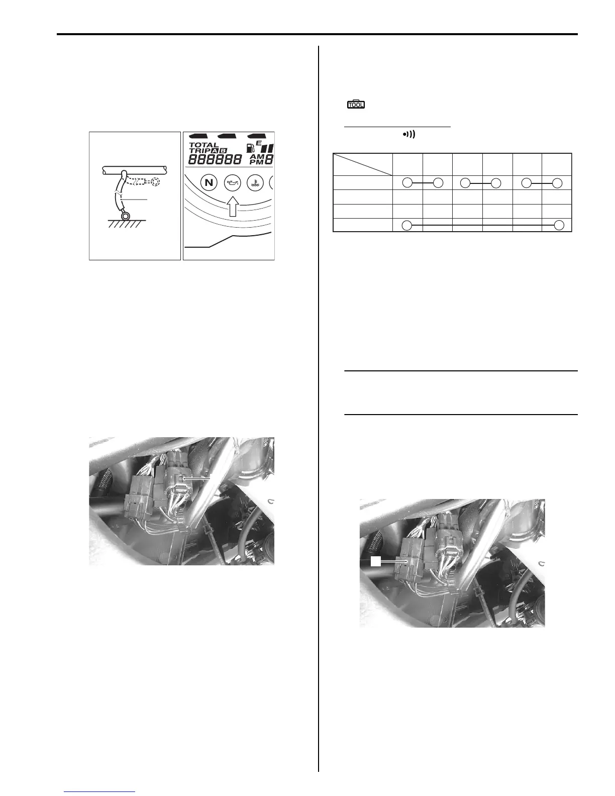
3) Check if the oil pressure indicator (LED) will light up
when grounding the lead wire (1).
If the oil pressure indicator does not light up, replace
the combination meter unit with a new one after
checking the connection of couplers.
Oil Pressure Switch Removal and Installation
B718H19306024
Refer to “Oil Pressure Switch Removal and Installation in
Section 1E (Page 1E-7)”.
Ignition Switch Inspection
B718H19306025
Inspect the ignition switch in the following procedures:
1) Remove the right frame head cover. (GSF1250/A)
Refer to “Exterior Parts Removal and Installation in
Section 9D (Page 9D-6)”.
2) Disconnect the ignition switch coupler (1).
3) Inspect the ignition switch for continuity with a tester.
If any abnormality is found, replace the ignition
switch with a new one.
Special tool
: 09900–25008 (Multi-circuit tester set)
Tester knob indication
Continuity ( )
4) After finishing the ignition switch inspection, reinstall
the removed parts.
Ignition Switch Removal and Installation
B718H19306026
Refer to “Ignition Switch Removal and Installation in
Section 1H (Page 1H-9)”.
Horn Inspection
B718H19306027
NOTE
If the horn sound condition is normal, it is not
necessary to inspect the horn button
continuity.
Horn Button Inspection
1) Remove the right frame head cover. (GSF1250/A)
Refer to “Exterior Parts Removal and Installation in
Section 9D (Page 9D-6)”.
2) Disconnect the left handlebar switch coupler (1).
1
I718H1930036-02
1
I718H1930026-05
P
LOCK
OFF
ON
B/R B/O G/B B/W B/G Br/B
Color
Position
I649G1180025-02
1
I718H1930045-01

 Loading...


