Engine Electrical Devices: 1C-5
Installation
1) Remove the air cleaner cover and air cleaner
element. Refer to “Air Cleaner Element Removal and
Installation in Section 1D (Page 1D-6)”.
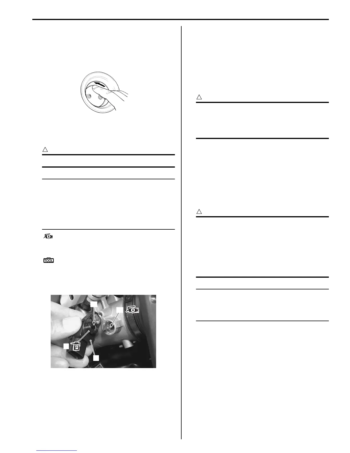
2) Close the secondary throttle valve by finger.
3) With the STV fully closed, install the STP sensor (1)
and tighten the STP sensor mounting screw to the
specified torque.
CAUTION
!
Replace the O-ring (2) with a new one.
NOTE
• Apply a thin coat of engine oil to the O-
ring.
• Align the secondary throttle shaft end “A”
with the groove “B” of STP sensor.
• Apply grease to the secondary throttle
shaft end “A” if necessary.
: Grease 99000–25010 (SUZUKI SUPER
GREASE A or equivalent)
Special tool
: 09930–11950 (Torx wrench)
Tightening torque
STP sensor mounting screw: 3.5 N·m (0.35 kgf-
m, 2.5 lb-ft)
4) Make sure the STP valve open or close smoothly.
5) Adjust the position of STP sensor. Refer to “STP
Sensor Adjustment (Page 1C-4)”.
6) Reinstall the removed parts.
STV Actuator Inspection
B718H11306031
Refer to “DTC “C28” (P1655): Secondary Throttle Valve
Actuator (STVA) Malfunction in Section 1A (Page 1A-
73)”.
STV Actuator Removal and Installation
B718H11306032
Refer to “Throttle Body Disassembly and Assembly in
Section 1D (Page 1D-10)”.
CAUTION
!
• Never remove the STVA from the throttle
body.
• The STVA, IAP/TP/IAT sensor and throttle
body are available only as an assembly.
ISC Valve Inspection
B718H11306027
Refer to “DTC “C40” (P0505 / P0506 / P0507): ISC Valve
Circuit Malfunction in Section 1A (Page 1A-91)”.
ISC Valve Removal and Installation
B718H11306028
Refer to “Throttle Body Disassembly and Assembly in
Section 1D (Page 1D-10)”.
CAUTION
!
Be careful not to disconnect the ISC valve
coupler at least 5 seconds after ignition
switch is turned to OFF. If the ECM coupler or
ISC valve coupler is disconnected within 5
seconds after ignition switch is turned to
OFF, there is a possibility of an unusual valve
position being written in ECM and causing an
error of ISC valve operation.
NOTE
When the ISC valve is removed or replaced,
the ISC valve or new one should be set to
Preset position. Refer to “ISC Valve Preset
and Opening Initialization (Page 1C-6)”.
I718H1130017-01
1
2
“B”
“A”
I718H1130009-01

 Loading...


