1D-40 Engine Mechanical:
Cam Chain Tensioner Inspection
B718H11406015
Inspect the cam chain tensioner in the following
procedures:
1) Separate the crankcases, upper and lower. Refer to
“Engine Bottom Side Disassembly (Page 1D-53)”.
2) Remove the crankshaft assembly from the upper
crankcase. Refer to “Engine Bottom Side
Disassembly (Page 1D-53)”.
3) Remove the dampers (1) of the cam chain tensioner.
4) Remove the cam chain tensioner (2) and pin.
5) Check the contacting surface of the cam chain
tensioner. If it is worn or damaged, replace it with a
new one.
6) Install the pin, cam chain tensioner and dampers.
7) Reinstall the crankshaft assembly. Refer to “Engine
Bottom Side Assembly (Page 1D-61)”.
8) Reassemble the crankcases, upper and lower. Refer
to “Engine Bottom Side Assembly (Page 1D-61)”.
Cylinder Head Disassembly and Assembly
B718H11406016
Refer to “Engine Top Side Disassembly (Page 1D-24)”.
Refer to “Engine Top Side Assembly (Page 1D-28)”.
CAUTION
!
Identify the position of each removed part.
Organize the parts in their respective groups
(i.e., intake, exhaust, No.1 or No.2) so that
they can be installed in their original
locations.
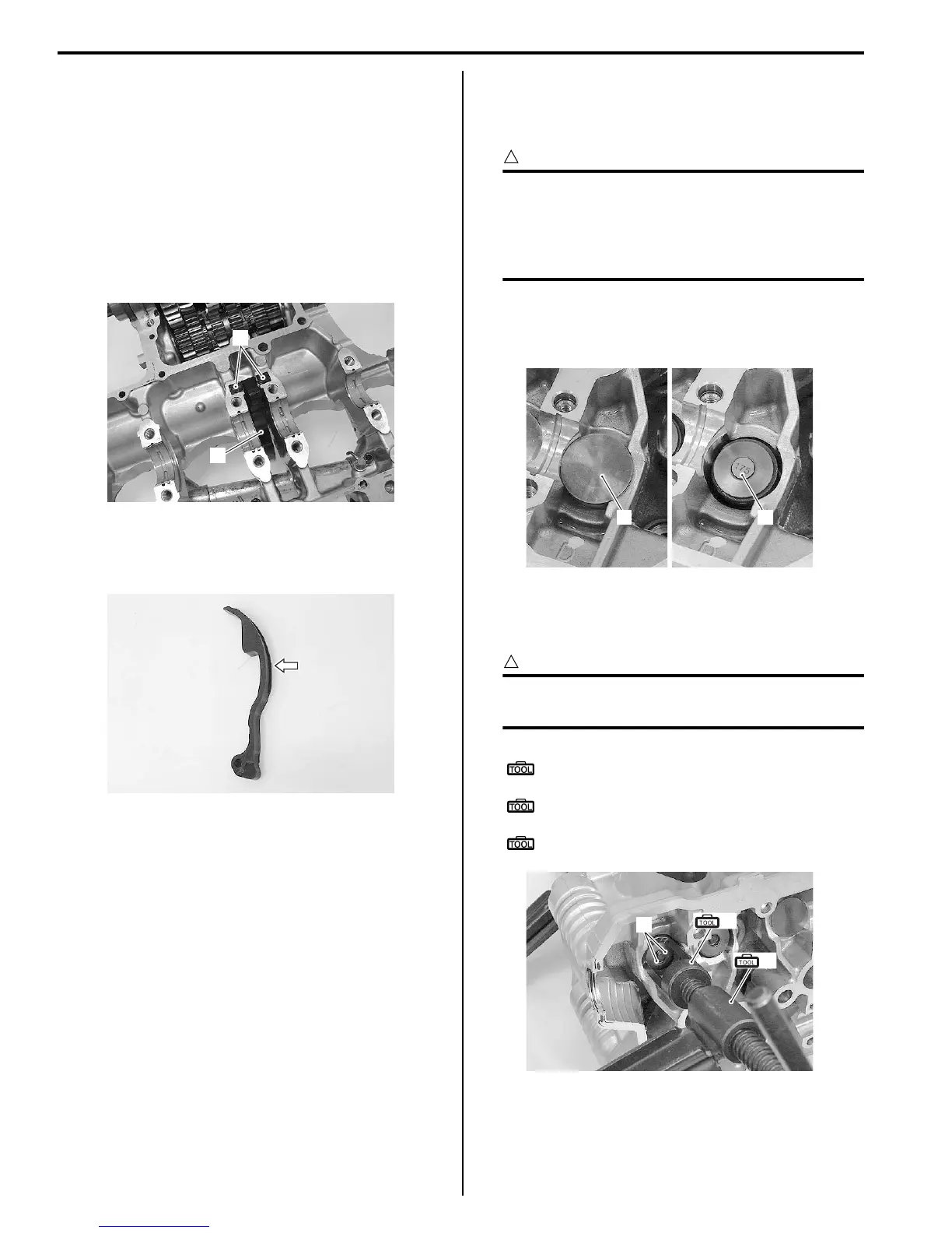
Disassembly
1) Remove the tappet (1) and shim (2) by fingers or
magnetic hand.
2) Using the special tools, compress the valve spring
and remove the two cotter halves (3) from the valve
stem.
CAUTION
!
Be careful not to damage of the tappet sliding
surface with the special tool.
Special tool
(A): 09916–14510 (Valve spring
compressor)
(B): 09916–14521 (Valve spring compressor
attachment)
: 09916–84511 (Tweezers)
1
2
I718H1140096-01
I718H1140097-01
1
2
I718H1140098-01
(B)
(A)
3
I718H1140100-01

 Loading...


