3 - 6
Operation panel
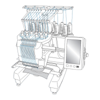
Main unit
Assembly
Assembly
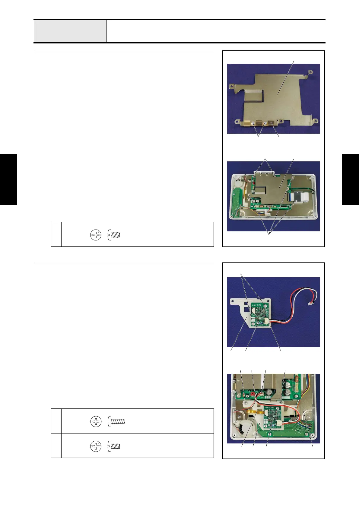
8 Panel PCB case attachment
1. Attach the ground plate USB 1 to the panel PCB case 2 with the 2 screws
1.
2. Attach the panel PCB case 2 to the PCB base plate with the 5 screws 2.
1
2
2
2
2
2
1 1
Screw, Bind
M3X5
9 Back light drive PCB attachment
1. Attach the back light drive PCB 1 to the PCB holder ASV relay 2 with
the 2 screws 1.
2. Connect the lead wire assy 3 to the back light drive PCB 1.
3. Attach the PCB holder ASV relay 2 to the PCB base plate 4 with the 2
screws 2.
4. Connect the back light FPC 5 and lock the lock of the connector.
5. Connect the connector 6 of the back light drive PCB 1 to the panel PCB
assy 7.
*Key point
• Refer to “Special Instructions of Wiring”.
1
2
2
1
62
45 2
7
1
312
Taptite, Bind B
M3X8
Screw, Bind
M3X5

 Loading...