4 - 35
Inspection and
Adjustment
Inspection and
Adjustment
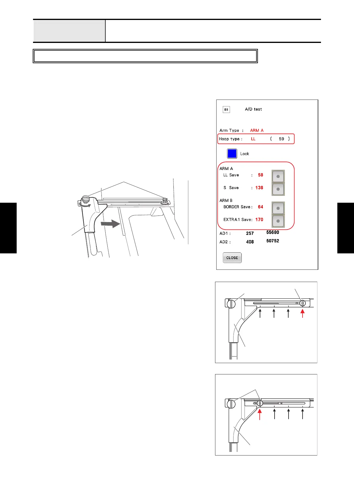
Adjustment Hoop sensor (A/D value)
[Standard]
The attached frame type and the displayed frame type on the screen are the same types.
[Adjustment]
1. Attach the tubular round arm set A to the carriage.
2. Start the test mode and select [#08: A/D test] under [MAIN
BOARD TEST MODE].
3. Press the [Lock] (blue button) to unlock the A/D value of the
hoop sensor.
*Key point
• When the lock of the A/D value of the hoop sensor is
unlocked, [Unlock] is displayed.
4. Press the [LL Save] after attaching the left arm of the tubular
round arm set A to the position 1 (refer to Fig.1) and tightening
the 2 thumb screws certainty.
*Key point
• Save the A/D value of the hoop sensor to the flash memory
the sewing machine at the attachment position
2 of the LL
frame.
5. Press the [S Save] after attaching the left arm of the tubular round
arm set A to the position 4 (refer to Fig.2) and tightening the 2
thumb screws certainty.
*Key point
• Save the A/D value of the hoop sensor to the flash memory
the sewing machine at the attachment position
4 of the S
frame.
To next page
After replace the hoop lever (potentiometer) and the hoop PCB assy, need to adjust.
Thumb screw
Left arm
Thumb screw
Arm A
Thumb screw
4 3 2 14321
Fig.1
Thumb screw
Arm A
5 34 33
23
1
Fig.2

 Loading...