4 - 37
Inspection and
Adjustment
Inspection and
Adjustment
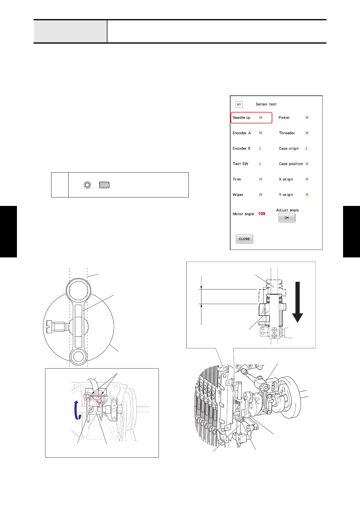
Adjustment Upper shaft encoder phase
[Standard]
When the jump bracket is lowered 19.5 to 20.0 mm from the top dead center position, [Needle up] signal display
should be changed from [H] to [L].
[Adjustment]
1. Start the test mode and select [#07: Sensor test] under [MAIN BOARD
TEST MODE].
2. Turn the pulley counterclockwise by hand in view from the rear side of
the machine until the jump bracket is lowered 19.5 to 20.0 mm from
the top dead center position (= the crank rod is in a vertical position).
3. Loosen the screw 1 of the encoder base.
4. Turn the encoder base clockwise (direction “A”) in view from the rear
side of the machine until [Needle up] signal display changes from [H]
to [L], and then tighten the screw 1 of the encoder base. (Fig.1)
1
Set Screw, Socket (CP)
M4X6
A
Top dead senter position
Base needle bar
Crank rod
19.5 - 20.0 mm
Thread take-up cam
Not contact
Encoder base
Fig.1
1
Jump bracket
Jump bracket
Base needle bar
Base needle bar
Thread take-up cam
Crank rod
with hex wrench 2 mm

 Loading...