6 - 20
Replacement
Maintenance &
Replacement
Maintenance &
Replacement
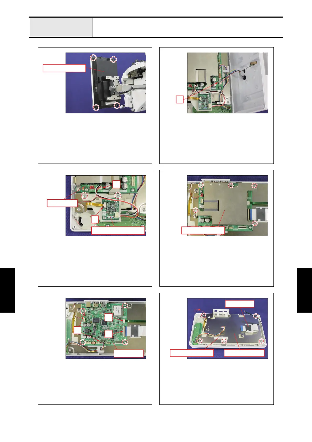
Panel PCB and LCD module
12
34
56
Back light drive PCB
Panel PCB
Panel PCB case
Panel rear cover
Panel PCB
PCB base plateBoard supporter
Ferrite core
A
A
B
C
B
A
- Remove the 4 screws, and then remove the panel rear
cover.
- Disconnect the connector of the lead wire assy. "A"
- Disconnect the connector of the back light drive PCB
from panel PCB.
"A"
- Unlock the lock of connector, and then disconnect the
FFC.
"B"
- Remove the 2 screws, and then remove the back light
drive PCB holder from the PCB base plate.
- Remove the 5 screws, and then remove the panel PCB case.
- Pull out the FFC from the ferrite core.
- Remove the borad supporter from the PCB base
plate.
- Remove the 5 screws from the PCB base plate.
- Disconnect the 2 connectors from panel PCB.
"A"
- Unlock the lock of connector, and then disconnect the
FFC.
"B"
- Unlock the lock of connector, and then disconnect the
FFC.
"C"
- Remove the 4 screws, and then remove the panel
PCB.

 Loading...